+86 29 8881 0979

default

How to select waveguide components for satellite communication

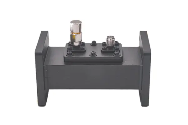
To select waveguide components for satellite communication, match their frequency (e.g., 12–18GHz for Ku-band) to the system’s operating range to minimize insertion loss (<0.5dB/cm). Use corrosion-resistant stainless steel or aluminum with joint gaps <0.1mm, and verify compliance with ITU-R S.465 standards for optimal signal integrity. Define Your Frequency Band​​ In satellite communications, this typically means […]

How to select waveguide components for satellite communication Read More »

What are the 5 latest trends in waveguide antenna technology

Recent waveguide antenna trends include: 26-40GHz millimeter-wave integration for 5G/satcom, boosting gain by 15% via 64-element phased arrays; carbon fiber composites reducing weight by 30% while maintaining <0.5dB insertion loss; RIS-enhanced designs improving beam efficiency by 5-8dB; and microchannel cooling enabling ±2℃ thermal stability at 100W/cm² power density. Integrated Antenna Design Over the past three

What are the 5 latest trends in waveguide antenna technology Read More »

How to troubleshoot waveguide antenna performance issues

To troubleshoot waveguide antenna performance, first measure VSWR with a tester (target <1.5; >1.5 indicates connector oxidation or misalignment). Use a 28GHz signal generator: if gain drops >2dB from spec, check waveguide flange joints for gaps. Rotate antenna to verify polarization—stable -30dBm±2dB signals confirm correct alignment. Ensure operation within 25±5℃, <60%RH to avoid thermal expansion

How to troubleshoot waveguide antenna performance issues Read More »

How to connect waveguide components to RF antennas

Connect waveguide components to RF antennas using precisely aligned flanges (e.g., CPR-229) to minimize signal loss. Seal joints with conductive gaskets or copper tape to maintain an airtight, low-VSWR interface (<1.2:1 ideal). Use a torque wrench to tighten flange bolts to the specified value (e.g., 25 in-lbs) for consistent electrical continuity. ​​Waveguide and Antenna Interface

How to connect waveguide components to RF antennas Read More »

What is the role of waveguide duplexers in communication systems

Waveguide duplexers are crucial for allowing a single antenna to simultaneously transmit and receive signals, often operating in frequency ranges like 3.5-4.2 GHz. They use internal filters to provide high isolation, typically over 30 dB, preventing powerful transmitted signals from overwhelming sensitive receivers, which is vital in radar and cellular systems. What is a Waveguide

What is the role of waveguide duplexers in communication systems Read More »

What are the 4 advantages of waveguide amplifiers over RF amplifiers

Waveguide amplifiers surpass RF amplifiers with higher frequency support (30-300GHz vs. <6GHz), lower insertion loss (<0.5dB vs. 1.2dB typical), 2-3× greater power capacity (100W+ vs. 20-30W), and broader bandwidth (>10GHz vs. ≤2GHz), optimizing high-frequency transmission efficiency. ​​Handles High Power Signals​​ While a typical coaxial-based RF amplifier might comfortably handle powers up to 500 watts, it

What are the 4 advantages of waveguide amplifiers over RF amplifiers Read More »

How to reduce insertion loss in waveguide assemblies

To reduce waveguide assembly insertion loss, optimize surface roughness (Ra≤0.2μm, cutting 30% loss vs. Ra=1μm), align with <λ/100 gap (e.g., <0.25mm in X-band for 15% reduction), and use low-loss materials like gold-plated copper to minimize resistive losses. Check Connector Alignment Studies indicate that a lateral offset of just ​​0.1 mm​​ in a standard WR-90 waveguide

How to reduce insertion loss in waveguide assemblies Read More »

What are the 6 critical waveguide assembly specifications

The six critical waveguide assembly specifications are operating frequency (e.g., 18-110 GHz), precise internal dimensions (±0.1 mm tolerance), low voltage standing wave ratio (VSWR <1.15:1), material (often aluminum or copper), surface finish (typically <1 µm Ra), and power handling capacity, which can exceed hundreds of kilowatts for pressurized systems. Operating Frequency Range The fundamental operating

What are the 6 critical waveguide assembly specifications Read More »

What are the 5 common waveguide antenna configurations

The five common waveguide antenna configurations include rectangular waveguides operating at 2–110 GHz, horn antennas achieving up to 25 dBi gain, slot arrays for precision radar systems, dielectric rod antennas for millimeter-wave applications, and parabolic reflectors often used with feed horns for high-directivity satellite communication exceeding 30 dBi. Rectangular Waveguide Basics From 5G base stations

What are the 5 common waveguide antenna configurations Read More »

How to design a waveguide antenna for high-frequency signals

Designing a high-frequency waveguide antenna requires precise calculation of its internal dimensions to support the desired propagation mode, typically using a width of at least 0.7λ for the dominant mode. Careful selection of low-loss materials like copper and rigorous simulation for impedance matching are critical to minimize signal attenuation and maximize power transfer efficiency. Understanding

How to design a waveguide antenna for high-frequency signals Read More »

Scroll to Top
Blank Form (#3)