
Confirm Endpoints
Identify the antenna-side and equipment-side connection positions, orientation and available installation space.
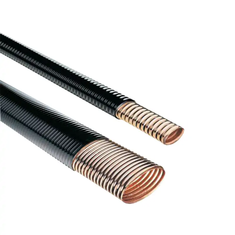
Elliptical waveguides and transitions are essential for efficiently guiding microwave and RF signals through complex system architectures. They facilitate seamless transitions between different waveguide formats, ensuring optimal signal integrity and minimal loss. These components are widely used in telecommunications, radar systems, and satellite communications for their superior performance in tight spaces and curved paths.
The required waveguide length should be determined from the actual installation route rather than the straight-line distance between the antenna and equipment. Include vertical and horizontal routing, bends, equipment-entry positions, support spacing, connector allowance and service access.
Identify the antenna-side and equipment-side connection positions, orientation and available installation space.
Mark E-plane and H-plane bends separately and compare them with the minimum bend radius of the selected model.
Plan hangers, standoffs and clamps without forcing the feeder into a tighter radius or unsupported route.
Include the transition, connector, splice and flange dimensions when calculating the overall installed length.
Verify length, flange faces, routing direction, accessories and installation clearances before production.
Elliptical waveguide does not use one universal bend radius in every direction. The permitted radius depends on whether the route bends through the narrow or broad dimension of the elliptical cross-section.
Mark each bend direction on the routing drawing and compare it with the model-specific E-plane and H-plane values in the technical table. Twisting and repeated bending should also be minimized during installation.
Check the published E-plane radius for the exact waveguide core. Listed E-plane values are generally smaller than the corresponding H-plane values.
Check the larger H-plane bend-radius requirement and ensure the route provides enough clearance around towers, walls, cabinets and antenna structures.
Factory-terminated and field-terminated delivery formats serve different installation requirements. The preferred format depends on route accessibility, transport limitations, on-site tools and the level of installation control required.
Waveguide is cut to the specified length and supplied with the selected termination components installed before shipment.
A continuous waveguide length can be routed first and terminated at the installation site using the applicable tools and components.
Long or access-restricted routes may be divided into manageable sections with compatible splice and transition components.
Two parts may share the same nominal waveguide size but still use different flange standards, hole patterns, sealing faces or mounting orientations.
Confirm the full flange designation and, where possible, provide the mating-component drawing. This helps prevent incompatibility between the transition, equipment port, antenna interface, gasket and fasteners.
Installation practices should protect the corrugated core, jacket and termination interfaces from excessive bending, twisting, impact, contamination and water entry.
Avoid local kinks and do not force the feeder around sharp corners or structural obstructions.
Align the feeder naturally with the route and connector orientation before fixing supports.
Position clamps and hangers so that the waveguide is supported without crushing or deforming the jacket.
Protect open ends and flange faces before connection, especially during outdoor installation.
Published values are tied to specific models, frequencies and test conditions. System performance also depends on route length, transitions, flanges, connectors, installation quality and operating environment.
Waveguide loss is commonly published per 100 metres at stated frequencies. Estimate the feeder contribution using the selected model and actual installed length, then include transition and connector losses separately.
The complete route may contain several interfaces. Confirm whether the stated VSWR applies to the waveguide core, adapter or complete terminated assembly before comparing alternatives.
Published peak-power values should be reviewed together with frequency, altitude, pressure, moisture, flange condition, pulse characteristics and the lowest-rated component in the system.
Providing complete application and interface information helps reduce repeated confirmation and makes it easier to review the correct waveguide, transition and accessories together.
These product groups can be reviewed when the feeder route requires rigid sections, direction changes, sealing, mechanical support or equipment-interface adaptation.
Send the operating band, power level, required length, bend layout, equipment-side flange, antenna-side flange, installation environment and quantity for a model and configuration review.







