
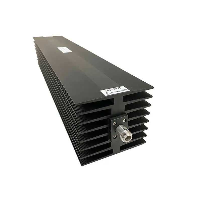
Coaxial Fixed Attenuators
Coaxial fixed attenuators selected by operating band, attenuation, power, impedance, connector and mechanical limits. Send your RF conditions for model review.
Send the RF Conditions. We Match the Configuration.
For a useful quotation, send the operating band, attenuation, power, impedance, connector arrangement and mechanical limits. We review those details before confirming the suitable attenuator configuration.
What We Need to Check the Right Attenuator
Model-specific values are confirmed after the configuration is selected. Send the items below instead of guessing from a general product range.
Operating Frequency
Start and stop frequency, plus any sub-band that must remain within specification.
Attenuation Requirement
Nominal dB value and any accuracy or flatness requirement that matters in your RF path.
Power Conditions
Average or CW power. For pulsed systems, also provide peak power, pulse width and duty cycle.
Impedance & VSWR
Required system impedance and the VSWR limit if your design has a defined acceptance value.
Connector Arrangement
Connector series, male/female interface and input/output arrangement required by the existing line.
Mechanical Limits
Maximum envelope, mounting method, installation space and thermal constraints that affect the build.
Already Have a Part Number, Drawing or Datasheet?
Send it with the required quantity and operating conditions. We can use it as the starting point for the configuration review.
What Happens After You Send the Requirement
The goal is to remove interface and specification ambiguity before the order is finalized.
Requirement Check
We review the operating band, attenuation, power and requested interface.
Configuration Match
We match the electrical and mechanical requirement to the available configuration.
Technical Confirmation
Available technical documentation is provided for confirmation before final order placement.
Order Support
Any agreed connector, dimensional or documentation details stay tied to the selected configuration.
Details That Prevent the Wrong Configuration
These details are useful when the attenuator must replace an existing part or fit into a fixed RF assembly.
Existing Part Reference
Manufacturer part number, label photo or existing datasheet.
Connector Detail
Series, gender and any adapter currently used next to the attenuator.
Installation Envelope
Available length, diameter/width, mounting clearance and cable direction.
Operating Conditions
Ambient temperature or other environmental limits when they affect the requested build.
Quantity
Prototype quantity, production quantity or expected repeat requirement.
Required Documentation
Tell us what technical or order documentation must be reviewed before purchase.
Continue Along the Same RF Path
Use the related product pages when the attenuator must be coordinated with another coaxial or waveguide interface.
Quick Answers Before You Inquire
What information should I send for a quotation?
Send frequency range, attenuation, power, impedance, connector type/gender, mechanical limits, quantity and any required documentation.
Can I send an existing part number or drawing?
Yes. A current part number, datasheet, label photo or drawing can be used as the starting reference together with your operating conditions.
Are all electrical values fixed across the product family?
No. Frequency, attenuation, power, connector and mechanical values depend on the selected configuration. Confirm the final values against the applicable technical documentation.
What warranty does Dolph publish?
Dolph Microwave publishes a one-year warranty from the date of delivery for defective material and workmanship, subject to its stated warranty terms.
Send the Six Details That Define Your Build
Frequency · attenuation · power · impedance · connector · mechanical limits.
Check the exact model row before quotation
Pages 4–7 of the Dolph Coaxial Components PDF list the fixed-attenuator models with model-specific average power, peak power, frequency range, VSWR, nominal attenuation, connector type and impedance. These limits are not interchangeable across the series.







