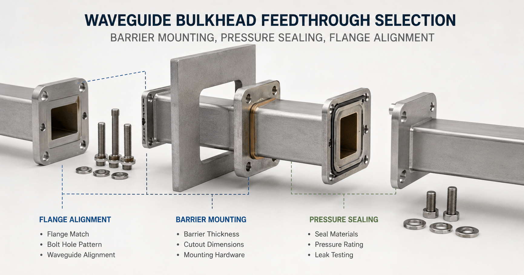
A waveguide bulkhead feedthrough should not be selected by waveguide size alone. It is simultaneously an RF transmission interface, a mechanical penetration through a wall or enclosure, and—in many installations—a controlled pressure boundary. A feedthrough that fits the nominal WR size can still fail in service if the wall thickness is wrong, the cutout interferes with the body, the gasket is incompatible with the operating environment, or the mating flanges are pulled together out of alignment.
The selection process should therefore begin with the complete installation stack: the barrier, feedthrough body, sealing interfaces, mating waveguides, hardware, operating pressure and required verification method. The approved mechanical drawing should control the installation rather than dimensions copied from a similar component or an earlier project.
Core selection principle: treat the barrier mounting, pressure seal and waveguide flange as one connected interface. A correction made in one area—such as enlarging a cutout or increasing bolt torque—can create a new sealing or RF alignment problem elsewhere.
| Selection Area | Required Project Input | Main Risk if Unconfirmed |
|---|---|---|
| Barrier mounting | Finished wall thickness, material, cutout, access and backing structure | Insufficient engagement, panel distortion or installation interference |
| Pressure sealing | Gas or fluid, differential pressure, temperature, seal material and allowable leakage | Seal extrusion, compression loss, permeation or an unverified pressure boundary |
| Flange alignment | Waveguide size, flange designation, aperture, bolt pattern, gasket groove and alignment features | Reflection, leakage, damaged mating faces or uneven gasket compression |
| Verification | RF test, dimensional report, pressure test and leak-test acceptance criteria | A component that fits mechanically but cannot demonstrate system compliance |
Dolph Microwave supplies waveguide bulkhead feedthroughs with standard and project-specific mechanical configurations. Before requesting a quotation, buyers should provide the complete barrier and flange interface rather than only the operating frequency.
Table of Contents
Barrier Mounting Method
The mounting arrangement determines how structural load, sealing force and waveguide alignment are transferred through the barrier. Common project layouts include a feedthrough clamped through a sheet-metal wall, a flanged body mounted against a structural plate, or a specially designed penetration integrated into a welded or brazed enclosure assembly.
These layouts are not automatically interchangeable. A mounting method suitable for a thin equipment cabinet may not be appropriate for a thick environmental chamber wall, while a rigid welded installation may require different inspection and replacement provisions from a removable clamped assembly.
Barrier Thickness
Barrier thickness should be measured as the complete installed stack, not only the nominal metal sheet. Depending on the design, the stack may include:
- The structural wall or enclosure panel
- Backing plates or reinforcement rings
- Surface coatings that affect the sealing land
- Insulating or isolation layers located inside the clamped joint
- External and internal mounting plates
- Washers, retainers or compression plates specified by the drawing
The feedthrough body length, available thread engagement and sealing-surface position must match this finished stack. If the body is too short, the mounting hardware may not achieve the required engagement. If it is unnecessarily long, the waveguide run may be displaced from its intended support position or interfere with nearby equipment.
Thin enclosure panels also require attention. Tightening a rigid feedthrough against unsupported sheet metal can bow the panel and create an uneven sealing surface. A backing ring or structural mounting plate may be required to distribute the clamp load. The backing component should be designed around the actual load path rather than added after leakage is discovered.
For thick walls, confirm whether the project requires an extended waveguide section, a removable sleeve, a two-piece assembly or a custom body length. Do not assume that a longer feedthrough can be produced by simply extending the outside dimensions. Waveguide straightness, internal surface continuity and flange orientation still have to be controlled.
Drawing requirement: state the finished barrier thickness with its tolerance and identify which face is the installation datum. A nominal statement such as “approximately 10 mm” is not sufficient for a controlled penetration.
Cutout Dimensions
The barrier cutout is not the same dimension as the waveguide aperture. The opening must clear the external feedthrough body and any manufacturing features that pass through the wall, while preserving enough material around the penetration for sealing and structural support.
The approved cutout drawing should define:
- Cutout width, height or diameter
- Corner radii
- Feedthrough centerline position
- Broad-wall and narrow-wall orientation
- Mounting-hole coordinates
- Datum edges and positional tolerances
- Clearance for welds, brazed joints, shoulders or body transitions
- Required flat sealing area around the opening
An oversized cutout may appear to make installation easier, but it can reduce the available gasket land, weaken a thin wall and make the feedthrough position dependent on loose mounting bolts. An undersized cutout can force installers to grind or file the wall during assembly, making it difficult to maintain dimensional control and surface protection.
The cutout should be deburred, cleaned and inspected before the feedthrough is installed. Burrs, weld spatter, paint ridges and machining marks can prevent a gasket or flange from sitting flat even when the main dimensions are correct.
IEC 60154-1 and IEC 60154-2 define mechanical requirements intended to support waveguide flange compatibility and electrical performance. The standards also note that drilling alignment holes after the flange has been mounted can improve alignment performance in applicable manufacturing processes.[1][2] This does not justify uncontrolled field drilling. Alignment and mounting features should be completed through an approved manufacturing or installation procedure.
Mounting Hardware
Mounting hardware is part of the mechanical and sealing design. A specification that states only “bolts included” leaves several important variables undefined.
| Hardware Item | Information to Confirm |
|---|---|
| Fastener size | Diameter, thread form, pitch and required length |
| Fastener material | Strength, corrosion resistance and compatibility with the flange and enclosure |
| Washers or load spreaders | Required type, location and suitability for the panel material |
| Thread engagement | Minimum engagement in tapped holes, inserts or nuts |
| Locking method | Lock washer, prevailing-torque nut, approved thread-locking compound or safety feature |
| Tightening requirement | Specified torque, tightening sequence and whether lubrication is permitted |
| Environmental compatibility | Humidity, salt exposure, vacuum, temperature cycling and galvanic-corrosion risk |
Bolts should not be used to force a feedthrough into a misaligned cutout. The component should sit naturally against its mounting surface before final tightening. If the body shifts significantly as the bolts are tightened, the cutout, hole pattern or supporting waveguide is probably imposing a side load.
For four-bolt patterns, progressive tightening in a diagonal or X-pattern helps distribute contact pressure. Keysight’s waveguide flange installation procedure instructs users to align the flanges with guide pins and gradually tighten the screws in an X-pattern to the final torque.[3] The actual torque value, however, must come from the approved component or project drawing. A generic torque copied from another flange may damage threads, distort the flange or over-compress the seal.
The hardware material should also be reviewed together with the feedthrough, enclosure and surface finish. Dissimilar metals exposed to moisture can create a galvanic-corrosion risk. In high-vibration installations, the locking method must prevent loosening without contaminating the RF or sealing surfaces.
Pressure Sealing
A pressurizable waveguide feedthrough may contain more than one sealing interface. The barrier-to-feedthrough joint prevents leakage around the wall penetration, while the waveguide flange joint seals the connected RF path. Some designs also contain an internal pressure window or permanently joined section.
These interfaces should be identified separately on the drawing and in the test plan. Passing a leak test on the feedthrough body alone does not prove that the final barrier installation will remain sealed after the mounting gasket, mating flange and field hardware are added.
Seal Materials
Seal material selection should begin with the operating environment, not with a familiar gasket name. The same elastomer can behave differently when exposed to high temperature, vacuum, dry nitrogen, outdoor weather, cleaning chemicals or long-term compression.
At minimum, evaluate the following:
- Operating and storage temperature
- Pressure direction and differential pressure
- Gas or fluid compatibility
- Compression set and expected service life
- Permeation requirements
- Vacuum outgassing requirements
- Humidity, ozone and ultraviolet exposure
- Required electrical conductivity or EMI continuity
- Flange groove geometry and designed compression
- Replacement and maintenance intervals
A non-conductive gasket may provide pressure sealing while relying on direct metal-to-metal contact elsewhere for RF continuity. A conductive elastomer may combine environmental sealing and electrical bonding, but its filler system, compression range, contact resistance and galvanic compatibility must be verified for the actual flange materials.
Dolph Microwave lists conductive and non-conductive options for its die-cut waveguide gaskets, including conductive silicone and pressure-sealing elastomer options for different flange families. The gasket should still be selected against the project drawing; a material name alone does not establish the correct thickness, groove fill or compression.
Vacuum projects need an additional material review. NASA maintains an outgassing database based on total mass loss and collected volatile condensable material testing to support spacecraft material selection.[4] A seal that works in a pressurized terrestrial cabinet should not automatically be treated as vacuum compatible.
Material qualification data should identify the exact compound, hardness and manufacturer designation where the environment is critical. “Silicone gasket” is usually too broad because different silicone compounds can have substantially different mechanical, electrical and outgassing characteristics.
Pressure Rating
The term “pressure capable” is not a usable engineering rating. The purchase specification should state the pressure conditions that the assembled feedthrough must withstand.
| Pressure Input | Required Definition |
|---|---|
| Normal operating pressure | Expected continuous internal and external pressure |
| Maximum differential pressure | Maximum pressure difference across the penetration |
| Pressure direction | Internal-to-external, external-to-internal or bidirectional |
| Pressure medium | Dry air, nitrogen, helium, process gas, liquid or another medium |
| Temperature | Pressure rating at the minimum and maximum service temperature |
| Transient condition | Startup surge, rapid depressurization, transportation or emergency condition |
| Proof requirement | Required proof pressure and test duration, where applicable |
| Allowable leakage | Maximum permitted leak rate or pressure loss |
| Service cycle | Continuous pressure, repeated cycling or occasional pressurization |
The pressure boundary should be rated as an assembly. A thick feedthrough flange does not compensate for a weak enclosure panel, inadequate fasteners or an incorrectly compressed gasket. The lowest-rated part of the installation can control the usable system pressure.
Numeric pressure claims should be supported by an approved drawing, calculation or test report for the actual model and configuration. Avoid transferring a pressure value from another waveguide size merely because the products look similar. Flange area, body geometry, fastener spacing and seal dimensions may all be different.
NASA-STD-7012A distinguishes operating, design and proof-pressure concepts and requires leak-test pressure to be defined by the test article specification.[5] Although a commercial microwave installation is not automatically governed by NASA requirements, this is a useful engineering principle: pressure levels and acceptance criteria must come from the controlled product specification rather than from an informal installation assumption.
Leak Testing
Leak testing should verify the intended pressure boundary under a documented procedure. “Leak tested” is incomplete unless the report identifies the test method, pressure, medium, stabilization period, instrument and acceptance criterion.
A useful leak-test specification includes:
- The assembly configuration being tested
- The test medium and tracer-gas concentration, if applicable
- The internal and external pressure conditions
- The stabilization and hold time
- The operating temperature or permitted temperature range
- The test instrument and calibration status
- The required test sensitivity
- The maximum allowable leakage rate or pressure change
- The pass/fail decision
- The component serial number or batch traceability
Pressure-decay testing can be suitable for total leakage verification when the expected leakage is within the method’s sensitivity. However, pressure change is influenced by the internal volume, ambient temperature, test-article temperature and instrument accuracy. NASA-STD-7012A requires these variables to be monitored or considered when calculating leakage from pressure decay.[5] ASTM E2930 similarly requires test equipment, duration and sensitivity to be selected against the required leakage specification.[6]
Bubble testing can help locate a gross leak at a joint, but it should not be substituted for a quantitative method where the project specifies a numerical leakage limit. Helium mass-spectrometer methods can provide much greater sensitivity, but the procedure must define the test direction, tracer-gas preparation, background level, calibration and permissible leak rate.
The final leak test should include the sealing interfaces that will exist in service. Where practical, test the feedthrough after installation in a representative barrier using the specified gasket and mounting hardware. A factory test of the feedthrough body and a field test of the completed penetration serve different purposes.
After pressure verification, inspect the gasket position and mounting hardware again. A joint can pass an initial short-duration test yet remain unsuitable if the gasket is visibly extruded, unevenly compressed or exposed to a sharp edge.
Flange Alignment
Waveguide flange alignment affects both RF performance and sealing. Unlike a flexible hose connection, a rectangular waveguide joint contains a defined electromagnetic aperture. A lateral offset, angular mismatch, damaged mating surface or incorrectly oriented gasket creates a discontinuity at the connection.
Alignment should be established by the designed locating features and controlled mechanical datums. It should not depend on mounting-bolt clearance or on an installer pulling the flanges into position.
Flange Matching
Confirming the WR size is only the first step. The complete flange interface should be checked against the mating component.
- Waveguide size and internal aperture dimensions
- Flange standard and exact flange designation
- Cover, grooved, choke or other interface style
- Flange outside dimensions and thickness
- Bolt-hole count, size and thread arrangement
- Alignment-pin or dowel configuration
- Gasket groove position and dimensions
- Contact-face geometry
- Material and surface finish
- Broad-wall and narrow-wall orientation
IEC 60154-2 specifies dimensions for ordinary rectangular waveguide flanges with the aim of supporting mechanical compatibility, interchangeability and adequate electrical performance.[2] Referencing an IEC or EIA family is useful, but the purchase order should still identify the exact interface code and drawing revision.
A cover flange and a grooved flange may be designed as a mating pair, while two apparently similar flat faces may require a separate gasket arrangement. Do not determine compatibility from outside flange dimensions alone. The aperture, groove, locating features and sealing method must also match.
Dolph Microwave provides IEC- and EIA-style waveguide flange options as well as custom configurations. For a custom feedthrough, provide the mating-flange drawing or a controlled interface specification rather than only a flange name used by a previous supplier.
Bolt-Hole Pattern
The bolt-hole pattern performs two different functions: it supplies clamping force and, in some flange designs, contributes to coarse positioning. It should not be treated as a substitute for precision alignment pins, dowels, bosses or rings where those features are required.
The interface drawing should identify:
- Hole count and angular position
- Bolt-circle or rectangular coordinate dimensions
- Clearance holes versus tapped holes
- Thread size and depth
- Counterbores, countersinks or captive-hardware requirements
- Dowel-hole size and tolerance
- Fixed-pin position and projection
- Orientation marks or asymmetric features
NIST’s review of the IEEE 1785 waveguide-interface standards describes precision-dowel, ring-centered and plug-and-jack alignment mechanisms. It also explains that interface dimensional tolerances and linear or angular misalignment affect the waveguide reflection coefficient.[7] The direct lesson for bulkhead selection is that a flange being physically bolt-compatible does not guarantee equivalent electrical performance.
Do not enlarge RF flange holes in the field to correct a mismatched pattern. Enlarged holes may allow the bolts to enter, but they remove repeatable location control and can shift the waveguide apertures. If the barrier mounting holes require installation clearance, that clearance should be isolated from the precision RF flange interface through a properly designed mounting arrangement.
During assembly, engage all bolts by hand before applying final torque. If one bolt cannot enter without side loading, stop and correct the alignment. Keysight’s installation guidance states that when flange faces cannot be aligned without a gap, the screws should be loosened and the connection started again rather than forced closed.[3]
Waveguide Alignment
The waveguide centerline and aperture orientation should continue through the barrier without unintended offset or twist. This requires coordination between the barrier cutout, feedthrough body, flange locating features and the supports on both sides of the wall.
Three alignment conditions should be checked:
- Translational alignment: the two waveguide apertures are centered in the horizontal and vertical directions.
- Angular alignment: the mating faces are parallel and the connected waveguides do not meet at an angle.
- Rotational alignment: the broad and narrow walls are oriented correctly without unintended twist.
Linear and angular aperture misalignment can increase reflection at the joint. The effect becomes more sensitive as waveguide dimensions decrease and operating frequency increases. NIST’s discussion of IEEE 1785 specifically links interface dimensional tolerances and misalignment to electrical reflection performance.[7]
The connected waveguide runs should be independently supported. The feedthrough should not be used as a structural hanger for a long or heavy assembly. External bending or twisting load can tilt the flange, open part of the sealing interface and damage precision alignment features. Keysight’s waveguide handling guidance similarly instructs users to support the components and avoid applying bending or twisting force at the flange connection.[3]
A controlled installation sequence is:
- Verify part numbers, flange designations and drawing revisions.
- Inspect and clean the waveguide apertures, gasket groove and mating faces.
- Confirm that the barrier cutout and mounting holes are within tolerance.
- Install the feedthrough without fully tightening the barrier hardware.
- Support and align the connected waveguide sections.
- Engage alignment pins or locating features without force.
- Bring the flange faces into even contact.
- Engage all bolts by hand.
- Tighten gradually in the specified cross-pattern and to the specified torque.
- Complete dimensional, leak and RF verification required by the project.
Where RF performance is critical, final verification should include an appropriate network-analyzer measurement over the specified frequency band. A visual inspection can confirm that flange faces are seated, but it cannot quantify the reflection or insertion loss introduced by an imperfect interface.
Information to include with a waveguide bulkhead feedthrough inquiry:
| Category | Information Required |
|---|---|
| RF interface | Waveguide size, operating frequency range, power level and required RF performance |
| Flanges | Flange type on each side, mating drawings and gasket arrangement |
| Barrier | Material, finished thickness, cutout drawing, available mounting area and access |
| Mechanical layout | Overall length, centerline position, orientation and space restrictions |
| Pressure | Medium, operating pressure, maximum differential pressure, direction and temperature |
| Seal | Preferred compound, conductivity requirement, vacuum requirement and replacement policy |
| Environment | Indoor, outdoor, marine, vacuum, vibration, humidity or temperature cycling |
| Testing | Leak-test method, acceptance limit, proof requirement, RF test and reporting format |
| Documentation | Dimensional report, material record, plating record, pressure report and serial traceability |
A reliable selection is made from the complete interface specification—not from a catalog image or nominal waveguide designation. Barrier thickness controls the mechanical stack, the seal system controls pressure integrity, and flange geometry controls both repeatability and RF continuity.
For standard or customized requirements, review the available Dolph Microwave bulkhead feedthrough configurations and submit the barrier drawing, mating-flange details and pressure conditions through the Dolph Microwave contact page.
Technical References
- IEC 60154-1:2016 — Flanges for Waveguides, Part 1: General Requirements
- IEC 60154-2:2016 — Relevant Specifications for Flanges for Ordinary Rectangular Waveguides
- Keysight 85106D mm-Wave Network Analyzer System Installation and Operation Manual
- NASA Outgassing Data for Selecting Spacecraft Materials
- NASA-STD-7012A — Leak Test Requirements
- ASTM E2930-13(2021) — Standard Practice for Pressure Decay Leak Test Method
- NIST — A Review of the IEEE 1785 Standards for Rectangular Waveguides Above 110 GHz