
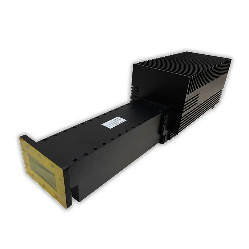
Waveguide Attenuators | High-Power Fixed Models, WR975 to WR28
Dolph Microwave supplies DH-series high-power fixed waveguide attenuators from 0.76 to 40 GHz, covering WR975 through WR28. The listed models provide 3–40 dB attenuation, 1.15:1 maximum VSWR, ±1.0 dB frequency response and model-dependent 0.5–10 kW CW power. Send your band, waveguide size, attenuation and flange pair for model confirmation before quotation.
Electrical Range and Model Coverage
Across the listed WHPFA models, the electrical baseline is 1.15:1 maximum VSWR, 3–40 dB attenuation and ±1.0 dB frequency response. CW power and flange designations change with waveguide size.
High-Power Fixed Model Matrix
Check the exact model row for frequency, waveguide size, CW power class and flange designation before releasing an RFQ. Final configuration should be confirmed against the selected model and project inputs.
| MODEL | FREQ. RANGE (GHz) | WG SIZE | VSWR Max. | ATT. (dB) | FREQ. RESPONSE (dB) | AVG POWER CW (KW) | FLANGES TYPE COVER | FLANGES TYPE GROOVED | MATERIAL | FINISH | DATASHEET |
|---|---|---|---|---|---|---|---|---|---|---|---|
| DH-9WHPFA… | 0.76-1.15 | WR975 | 1.15:1 | 3-40 | ±1.0 | 5~10 | UDR9 | PDR9 | Al | Chromate/Painted | PDF STEP |
| DH-12WHPFA… | 0.96-1.46 | WR770 | 1.15:1 | 3-40 | ±1.0 | 5~10 | UDR12 | PDR12 | Al | Chromate/Painted | PDF STEP |
| DH-14WHPFA… | 1.13-1.73 | WR650 | 1.15:1 | 3-40 | ±1.0 | 5~10 | UDR14 | PDR14 | Al | Chromate/Painted | PDF STEP |
| DH-22WHPFA… | 1.72-2.61 | WR430 | 1.15:1 | 3-40 | ±1.0 | 3~8 | UDR22 | PDR22 | Al | Chromate/Painted | PDF STEP |
| DH-26WHPFA… | 2.17-3.3 | WR340 | 1.15:1 | 3-40 | ±1.0 | 3~8 | UDR26 | PDR26 | Al | Chromate/Painted | PDF STEP |
| DH-32WHPFA… | 2.6-3.95 | WR284 | 1.15:1 | 3-40 | ±1.0 | 3~8 | UDR32 | PDR32 | Al | Chromate/Painted | PDF STEP |
| DH-40WHPFA… | 3.22-4.9 | WR229 | 1.15:1 | 3-40 | ±1.0 | 3~8 | UDR40 | PDR40 | Al | Chromate/Painted | PDF STEP |
| DH-48WHPFA… | 3.94-5.99 | WR187 | 1.15:1 | 3-40 | ±1.0 | 3~8 | UDR48 | PDR348 | Al | Chromate/Painted | PDF STEP |
| DH-58WHPFA… | 4.64-7.05 | WR159 | 1.15:1 | 3-40 | ±1.0 | 2~5 | UDR58 | PDR58 | Al | Chromate/Painted | PDF STEP |
| DH-70WHPFA… | 5.38-8.17 | WR137 | 1.15:1 | 3-40 | ±1.0 | 2~5 | UDR70 | PDR70 | Al | Chromate/Painted | PDF STEP |
| DH-84WHPFA… | 6.57-9.99 | WR112 | 1.15:1 | 3-40 | ±1.0 | 2~5 | UDR84/UBR84 | PDR84/PBR84 | Al | Chromate/Painted | PDF STEP |
| DH-100WHPFA… | 8.2-12.5 | WR90 | 1.15:1 | 3-40 | ±1.0 | 2~5 | UDR100/UBR100 | PDR100/PBR100 | Al | Chromate/Painted | PDF STEP |
| DH-120WHPFA… | 9.84-15 | WR75 | 1.15:1 | 3-40 | ±1.0 | 1~2 | UBR120 | PBR120 | Al | Chromate/Painted | PDF STEP |
| DH-140WHPFA… | 11.9-18 | WR62 | 1.15:1 | 3-40 | ±1.0 | 1~2 | UBR140 | PBR140 | Al | Chromate/Painted | PDF STEP |
| DH-180WHPFA… | 14.5-22 | WR51 | 1.15:1 | 3-40 | ±1.0 | 1~2 | UBR180 | PBR180 | Al | Chromate/Painted | PDF STEP |
| DH-220WHPFA… | 17.6-26.7 | WR42 | 1.15:1 | 3-40 | ±1.0 | 0.5-1 | UBR220 | PBR220 | Al | Chromate/Painted | PDF STEP |
| DH-260WHPFA… | 21.7-33 | WR34 | 1.15:1 | 3-40 | ±1.0 | 0.5-1 | UBR260 | PBR260 | Al | Chromate/Painted | PDF STEP |
| DH-320WHPFA… | 26.3-40 | WR28 | 1.15:1 | 3-40 | ±1.0 | 0.5-1 | UBR320 | PBR320 | Al | Chromate/Painted | PDF STEP |
For final ordering, confirm the selected model, attenuation value, CW power requirement and both flange interfaces with Dolph Microwave.
Part Number Guide
DH-100DRWHPFA30PMA2000
Finish Note
All Dolph-MW models include an surtec/corrosion protection treatment and are painted flat black. Flanges are unplated, polished and surtec. Other finishes and paint colors are available upon request.
Match the Attenuator Family to the Requirement
Use the high-power fixed matrix when the attenuation value is set and the required CW power falls within a published WHPFA model. For a different waveguide structure, power class or function, use the related family that matches the actual system.
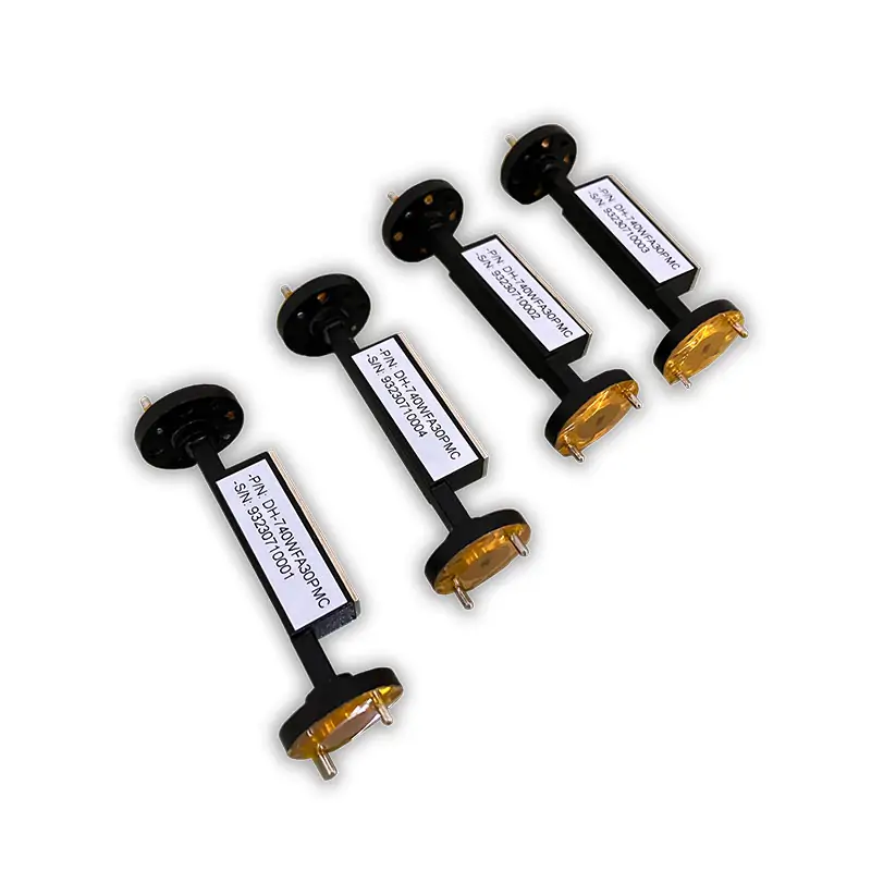
Standard Rectangular Fixed Attenuation
For lower-power standard rectangular models extending to higher millimeter-wave bands, review the Waveguide Fixed Attenuator range.
Double-Ridged High-Power Attenuation
For broadband double-ridged waveguide systems, review the separate High Power Fixed Attenuator model family.
Double-Ridged Precision Fixed Models
For lower published power ratings with double-ridged bandwidth, compare the Precision Fixed Attenuator range.
Power Absorption Instead of Inline Attenuation
If the requirement is to terminate a waveguide port and absorb power, use the High Power Termination family instead of an attenuator.
Confirm Power and Flange Interfaces Before Ordering
The model number does not replace the system inputs. Average power, pulse conditions, waveguide designation and both flange interfaces should be confirmed together before the final model is released.
Send the Inputs That Control the Quote
A complete RFQ lets the sales and engineering team compare your requirement against the published model matrix without guessing the interface or power condition.
Engineering and Supply Support
Dolph Microwave has been making microwave parts since 2001. Its custom high-power capability pages list machining, brazing, assembly and testing for standard and project-specific microwave components.
For broader custom high-power requirements, review the Custom High-Power Microwave Components capability page.
Dolph Microwave states a one-year warranty from the date of delivery for defects in material and workmanship, subject to the company warranty terms.
Request a QuoteTechnical Downloads
Keep the product specification and flange designation documents with the RFQ so the selected waveguide size, attenuation and interfaces can be checked against the same reference set.







