

Waveguide Phase Shifter & Septum Circular Polarizer
Published waveguide phase shifter configurations cover WR28 to WR284 with manual or motorized operation and continuous 0–360° phase adjustment. For septum circular polarizers, specify the operating bands, polarization, power and mechanical interfaces.
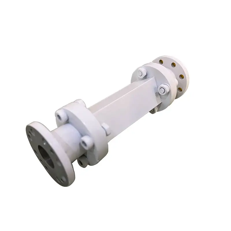
Product Data at a Glance
The published phase-shifter range and the septum circular-polarizer configurations serve different RF functions. Confirm the required function, band, waveguide interface, control method, polarization and power before selecting a model.
Key Features
Technical Specifications
Application Areas
Send the interface data before choosing a model
Include Rx/Tx frequency ranges, RHCP/LHCP requirement, power, flange, manual or motorized control, mechanical limits and quantity.
Published Phase-Shifter Range
A waveguide phase shifter changes the phase of the transmitted microwave signal. The current product page publishes the size range, operating modes and continuous phase-shift range above; numeric power, VSWR and insertion-loss limits must be confirmed for the selected model.
Separate the Required RF Function
This product page covers two related but distinct functions. The phase-shifter specifications must not be treated as polarizer performance, and polarizer configurations must not be used as universal phase-shifter model data.
Waveguide Phase Shifter
Published page data: WR-28 to WR-284, manual or motorized operation, wide bandwidth and 0-360° continuous phase shift.
Confirm model-specific frequency, power handling, VSWR, insertion loss, control arrangement, flange and mechanical limits in the quotation.
Septum Circular Polarizer
Specify the required Rx and Tx bands, RHCP/LHCP function, axial-ratio requirement, handling power, interfaces and common-port arrangement.
Confirm all model values and material information against the official datasheet and the approved interface drawing.
Download Official DatasheetOrdering Information
Confirm the mating interface
Use the Waveguide Flange Standard EIA & IEC reference when the mating flange is not fixed by an existing drawing.
For bolt pattern, sealing groove and EIA/IEC fit checks, see the Waveguide Flange Size Guide.
Confirm Flange and DrawingHow We Handle a Custom Build
For a wider system review, see Custom Antenna Feed Systems or the Manufacturing capability page.
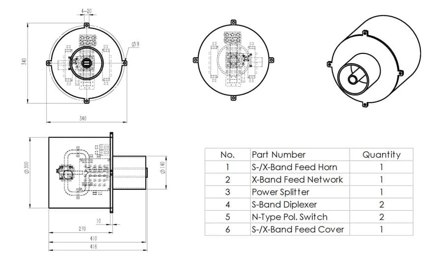
Complete the Feed Chain When Needed
Use the phase shifter and septum polarizer as one section of the feed network, then match the surrounding parts to the same frequency, polarization and interface requirements.
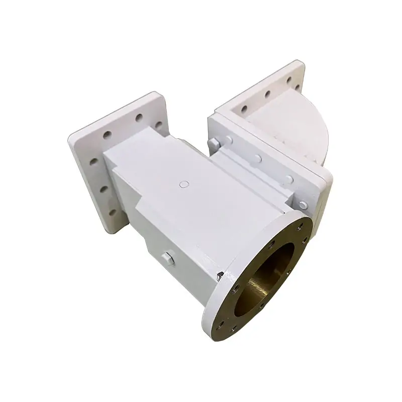
OMT (Orthogonal Mode Transducer)
Use when the feed assembly must separate or combine orthogonal polarization modes.
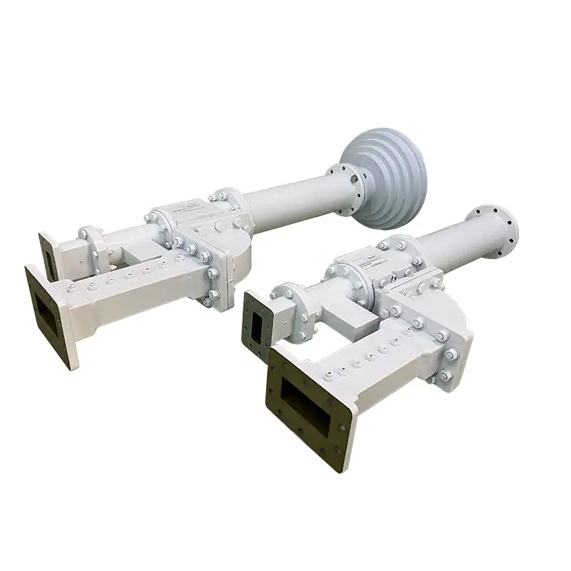
Waveguide Diplexer
Use when transmit and receive bands must be routed through one feed arrangement.
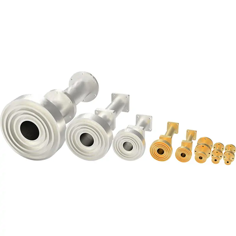
Microwave Feedhorn
Use when the polarization section must connect into a complete antenna feed assembly.
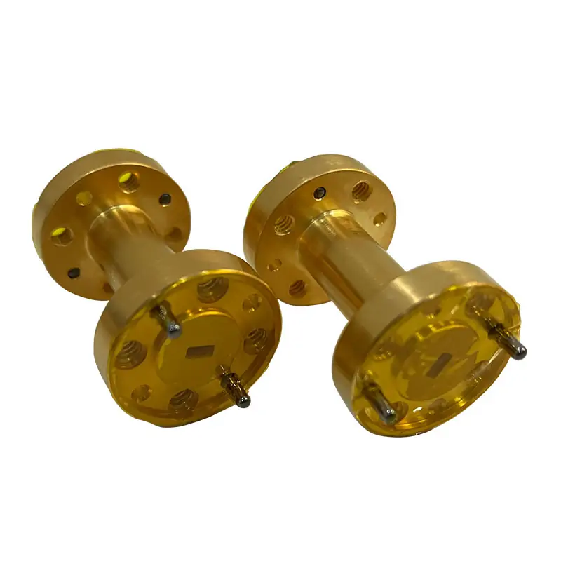
Rectangular to Circular Waveguide Transition
Use when the surrounding waveguide geometry requires a rectangular-to-circular interface change.
Factory and Quality Information
Request the current quality-system and compliance documents required for your supplier file or order approval.
Review Company Information



Send the requirement that controls the build
Send Rx/Tx bands, polarization, handling power, waveguide or flange interface, control preference, mechanical envelope, quantity and any existing drawing.







