
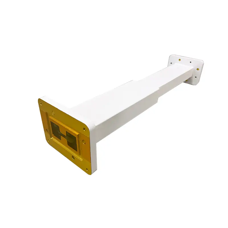
Choose the transition by the two interfaces, not the frequency alone.
The catalog gives you 32 starting configurations from 2.60 to 40.0 GHz. A useful match needs the operating band, the WRD side, the rectangular-waveguide side, both flange designations and enough space for the listed length.
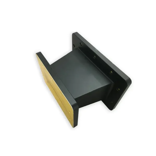
First check whether a standard row already fits your assembly.
Start with the actual mating hardware. The broader waveguide transition range is useful when both ends are standard waveguide. This page is specifically for a WRD double-ridged port on one side and a rectangular WR port on the other.
If all five items below line up with one model row, you have a strong catalog starting point. If one of them does not, send the drawing instead of forcing a near match.
Keep the quoted performance tied to the selected configuration.
The current product page contains two VSWR references. The structured model table is the safer ordering reference because every listed row carries its own specification.
What the model table says
All 32 standard rows below list VSWR 1.15, Al material, Chromate/Painted finish and Comply under RoHS & REACH.
That is the data you can compare model by model without mixing a family-level claim into a specific part.
What needs confirmation
The current narrative copy also mentions 1.06:1 for selected shared-band configurations. Do not apply 1.06:1 to every catalog row. If that limit matters to your system, put it in the RFQ and confirm it in the quoted model, drawing or test requirement.
Double-Ridge to Rectangular Transition Specifications
Every field from the current product table is kept separate. Scroll horizontally on smaller screens. Before release, confirm the complete part number and exact mechanical file for the selected row.
| MODEL | FREQ. RANGE (GHz) | VSWR | LENGTH (mm) | PORT 1 WAVEGUIDE | PORT 1 FLANGE TYPE | PORT 2 WAVEGUIDE | PORT 2 FLANGE TYPE | MATERIAL | FINISH | ROHS & REACH | DATASHEET |
|---|---|---|---|---|---|---|---|---|---|---|---|
| DH-250DRT32WA… | 2.60-3.95 | 1.15 | 135 | WRD250 | FPWRD250D30 | WR284 | UDR32 | Al | Chromate/Painted | Comply | DWGSTEP |
| DH-250DRT48WA… | 3.95-5.85 | 1.15 | 135 | WRD250 | FPWRD250D30 | WR187 | UDR48 | Al | Chromate/Painted | Comply | DWGSTEP |
| DH-250DRT58WA… | 4.90-7.05 | 1.15 | 135 | WRD250 | FPWRD250D30 | WR159 | UDR58 | Al | Chromate/Painted | Comply | DWGSTEP |
| DH-350DRT48WA… | 3.94-5.99 | 1.15 | 135 | WRD350 | FPWRD350D24 | WR187 | UDR48 | Al | Chromate/Painted | Comply | DWGSTEP |
| DH-350DRT58WA… | 4.90-7.05 | 1.15 | 135 | WRD350 | FPWRD350D24 | WR159 | UDR58 | Al | Chromate/Painted | Comply | DWGSTEP |
| DH-350DRT70WA… | 5.85-8.20 | 1.15 | 80 | WRD350 | FPWRD350D24 | WR137 | UDR70 | Al | Chromate/Painted | Comply | DWGSTEP |
| DH-475DRT70WA… | 5.85-8.20 | 1.15 | 130 | WRD475 | FPWRD475D24 | WR137 | UDR70 | Al | Chromate/Painted | Comply | DWGSTEP |
| DH-475DRT48WA… | 4.75-5.85 | 1.15 | 130 | WRD475 | FPWRD475D24 | WR187 | UDR48 | Al | Chromate/Painted | Comply | DWGSTEP |
| DH-475DRT84WA… | 7.05-10.0 | 1.15 | 135 | WRD475 | FPWRD475D24 | WR112 | UDR84/UBR84 | Al | Chromate/Painted | Comply | DWGSTEP |
| DH-475DRT100WA… | 8.20-11.0 | 1.15 | 135 | WRD475 | FPWRD475D24 | WR90 | UDR/UBR100 | Al | Chromate/Painted | Comply | DWGSTEP |
| DH-580DRT58WA… | 5.80-7.05 | 1.15 | 150 | WRD580 | FPWRD580D28 | WR159 | UDR58 | Al | Chromate/Painted | Comply | DWGSTEP |
| DH-580DRT70WA… | 5.90-8.40 | 1.15 | 135 | WRD580 | FPWRD580D28 | WR137 | UDR70 | Al | Chromate/Painted | Comply | DWGSTEP |
| DH-580DRT84WA… | 7.05-10.0 | 1.15 | 130 | WRD580 | FPWRD580D28 | WR112 | UDR84/UBR84 | Al | Chromate/Painted | Comply | DWGSTEP |
| DH-580DRT100WA… | 8.20-12.40 | 1.15 | 180 | WRD580 | FPWRD580D28 | WR90 | UDR/UBR100 | Al | Chromate/Painted | Comply | DWGSTEP |
| DH-580DRT120WA… | 10.0-15.0 | 1.15 | 101.6 | WRD580 | FPWRD580D28 | WR75 | UBR120 | Al | Chromate/Painted | Comply | DWGSTEP |
| DH-580DRT140WA… | 12.4-16.0 | 1.15 | 150 | WRD580 | FPWRD580D28 | WR62 | UBR140 | Al | Chromate/Painted | Comply | DWGSTEP |
| DH-580DRT180WA… | 15.0-16.0 | 1.15 | 130 | WRD580 | FPWRD580D28 | WR51 | UBR180 | Al | Chromate/Painted | Comply | DWGSTEP |
| DH-650DRT59WA… | 6.50-7.05 | 1.15 | 100 | WRD650 | FPWRD650D28 | WR159 | UDR58 | Al | Chromate/Painted | Comply | DWGSTEP |
| DH-650DRT70WA… | 6.50-8.20 | 1.15 | 80 | WRD650 | FPWRD650D28 | WR137 | UDR70 | Al | Chromate/Painted | Comply | DWGSTEP |
| DH-650DRT84WA… | 7.05-10.0 | 1.15 | 75 | WRD650 | FPWRD650D28 | WR112 | UDR84/UBR84 | Al | Chromate/Painted | Comply | DWGSTEP |
| DH-650DRT100WA… | 8.20-12.40 | 1.15 | 60 | WRD650 | FPWRD650D28 | WR90 | UDR/UBR100 | Al | Chromate/Painted | Comply | DWGSTEP |
| DH-650DRT120WA… | 10.0-15.0 | 1.15 | 50 | WRD650 | FPWRD650D28 | WR75 | UBR120 | Al | Chromate/Painted | Comply | DWGSTEP |
| DH-650DRT140WA… | 12.4-18.0 | 1.15 | 50 | WRD650 | FPWRD650D28 | WR51 | UBR140 | Al | Chromate/Painted | Comply | DWGSTEP |
| DH-650DRT180WA… | 15.0-18.0 | 1.15 | 60 | WRD650 | FPWRD650D28 | WR51 | UBR180 | Al | Chromate/Painted | Comply | DWGSTEP |
| DH-750DRT70WA… | 7.50-8.20 | 1.15 | 60 | WRD750 | FPWRD750D24 | WR137 | UDR70 | Al | Chromate/Painted | Comply | DWGSTEP |
| DH-750DRT84WA… | 7.50-10.0 | 1.15 | 60 | WRD750 | FPWRD750D24 | WR112 | UDR/UBR84 | Al | Chromate/Painted | Comply | DWGSTEP |
| DH-750DRT100WA… | 8.20-12.40 | 1.15 | 60 | WRD750 | FPWRD750D24 | WR90 | UDR/UBR100 | Al | Chromate/Painted | Comply | DWGSTEP |
| DH-750DRT120WA… | 10.0-15.0 | 1.15 | 60 | WRD750 | FPWRD750D24 | WR75 | UBR120 | Al | Chromate/Painted | Comply | DWGSTEP |
| DH-750DRT140WA… | 12.4-18.0 | 1.15 | 60 | WRD750 | FPWRD750D24 | WR62 | UBR140 | Al | Chromate/Painted | Comply | DWGSTEP |
| DH-750DRT180WA… | 15.0-18.0 | 1.15 | 60 | WRD750 | FPWRD750D24 | WR51 | UBR180 | Al | Chromate/Painted | Comply | DWGSTEP |
| DH-180DRT220WA… | 18.0-26.5 | 1.15 | 70 | WRD180 | FPWRD180C24 | WR42 | UBR220 | Al | Chromate/Painted | Comply | DWGSTEP |
| DH-180DRT320WA… | 26.5-40.0 | 1.15 | 70 | WRD180 | FPWRD180C24 | WR28 | UBR320 | Al | Chromate/Painted | Comply | DWGSTEP |
DWG and STEP are retained because they are shown in the current table. The public rendered page does not expose the individual model-file URLs, so this fragment does not guess them.
Keep the interface code visible when sales checks the request.
Use this only as the published coding example. The final quoted part number and approved drawing control the order.
“350DRT70”Waveguide SizeWRD350 to WR137“WA”Waveguide DRTypeWaveguide Transition“80”Length80 mm“P”Flange TypeFlat“M”Flange TypeGrooved“A/C”MaterialAluminium, CuSend the real interface instead of adapting your design around the wrong part.

A custom review makes sense when the drawing does not match a standard row.
That can be a non-standard flange, a fixed clocking angle, a tighter length limit, a different material or finish, or a transition that has to become part of a larger waveguide assembly.
A complete inquiry is easier to quote and harder to misread.
You do not need a finished engineering package to start. A clear sketch is useful if it shows both mating ends and the space the transition has to fit.
Send these details together.
If you already have a model number, include it. If not, the two port interfaces and operating band are the best starting point.
Ask for the checks your project actually needs.
Company capability is broader than one catalog line.
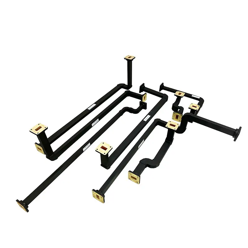
Dolph Microwave lists CNC machining, forming and bending, brazing and assembly, surface processing, and RF testing as company-level capabilities. That does not mean every test is automatically included with every transition.
Put the required dimensional checks, RF limits, drawing approval and records into the quotation. The current site also publishes a one-year warranty against defective material and workmanship.
Keep the existing PDF links and add the references that help selection.
The first two links below are retained from the current page. The other two are Dolph Microwave reference sheets that can help with adjacent waveguide-transition work.
The High Power Termination PDF is not a transition datasheet; it is kept here because it is already linked from the current product page and you asked that existing PDF downloads not be removed.
Other products buyers often need around the transition.
These are separate product families. Use them only when they match the next interface or routing function in your assembly.
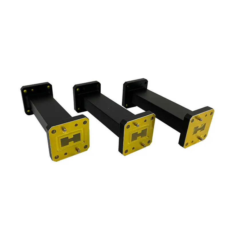
Double-Ridge to Double-Ridge Transition
Use when both interfaces remain in double-ridged waveguide but the WRD families differ.
View product →
Double-Ridged Waveguide Straights
Continue the WRD path with a drawing-controlled straight section and the required flange pair.
View product →
Rectangular to Circular Transition
Use when the next interface changes from rectangular waveguide to a circular section.
View product →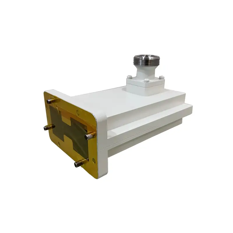
Double-Ridged Waveguide to Coaxial Adapter
Use when the RF path leaves WRD waveguide and needs a coaxial connector interface.
View product →Short answers to the points that usually stop a model decision.
Which model should I start with?
Find the row that covers your full operating band, then check the WRD size and FPWRD flange on Port 1, the rectangular WR size and UDR / UBR flange on Port 2, and the listed length. If any of those do not match the mating hardware, send the drawing for a custom review.
Is the VSWR 1.06:1 or 1.15?
The current 32-row model table lists 1.15 for every standard configuration. The product narrative also mentions 1.06:1 for selected shared-band configurations. Treat 1.15 as the published table value and confirm any lower requirement against the exact quoted model and acceptance test.
Can length, flange, material or finish be changed?
The current product information identifies custom length, flange, finish and material options. The part-number guide also includes Aluminium / Cu coding. Send the required variation with the mating drawing so the final configuration can be quoted rather than inferred from a standard row.
Are DWG and STEP files available?
DWG and STEP are shown in the current model table. Use the file tied to the final model and revision for mechanical approval. This HTML does not invent individual download URLs because the public page does not expose them.
Can the transition be supplied as part of a larger assembly?
Dolph Microwave publishes custom waveguide-assembly capability covering bends, twists, straight sections, flexible sections and end interfaces. Mark the full RF path and envelope on one drawing when you want the transition reviewed as part of the assembly.
What should I send if I do not know the part number?
Send the operating band, both waveguide sizes, both flange details, finished-length limit, a sketch or mating drawing, quantity and any controlled RF or documentation requirement. That is enough to start a model check.
Send both interfaces and the operating band. The rest can be checked from the drawing.
For a standard match, include the model row you are considering. For a custom build, include the mating drawing or a clear sketch with the available envelope.







