
Double-Ridged Waveguide Pressure Inlets
Pressure-inlet sections for WRD840 through WRD180 waveguide systems. Published model bands cover 0.84–40 GHz with VSWR 1.05:1. Choose the inlet thread, connector, tube O.D., section length, flange and material to match the actual waveguide run.
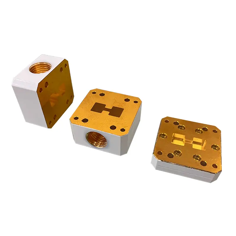
Match the inlet to the waveguide run, not just the frequency
A frequency match is only the start. A usable pressure inlet also has to bolt to the correct WRD flange, connect to the gas line, fit the available space and match the required sealing arrangement.
Use the actual waveguide family shown in the model table. Several bands overlap, so frequency alone may not identify the correct mechanical interface.
Select the published Schrader valve, Pagoda connector or push-in fitting and state how your dry-air or approved inert-gas line connects to it.
Published pneumatic tubing O.D. options are 4, 6, 8, 10, 12 and 16 mm. Include the actual tube size in the RFQ.
Choose the matching FPWRD flat / FMWRD grooved flange designation shown for the selected model. Check the mating part before release.
The current product overview states customizable configurations up to 150 PSI. Treat that as an overview statement, not a blanket rating. Final allowable pressure must follow the selected build and approved pressure boundary.
19, 108 and 152 mm serve different installation needs
The published part-number guide separates the three lengths by function. Pick the shortest section that still provides the fittings and monitoring arrangement your system needs.
Flange spacer inlet
Published as a 19 mm flange spacer inlet. Use this when the project needs a compact gas-entry section and the required connection can be packaged in the available space.
Pressurizing section with Schrader valves
The published guide identifies 108 mm as a pressurizing section with Schrader valves. Confirm valve location, access and flange orientation on the drawing.
Pressurizing section with gauge
The published guide identifies 152 mm as a pressurizing section with Schrader valves and a pressure gauge. Confirm gauge orientation and installation clearance before production.
Length is not only an overall-size decision. It changes the available hardware and monitoring arrangement, so show nearby components, access space and preferred gauge direction on the RFQ drawing.
Confirm the thread standard before the drawing is released
The current page contains two different thread descriptions. The detailed product note identifies G threads, while older overview wording mentions NPT. Do not treat them as interchangeable.
Published G-thread options
- State the required thread standard explicitly on the RFQ.
- If replacing an existing inlet, send the mating fitting or thread drawing.
- Do not approve a build from nominal size alone.
Published connector options
- Schrader versions can be supplied with cap; the example code also shows a gauge version.
- Pagoda and push-in styles should be matched to the actual hose/tube connection.
- Include tube O.D. and access direction in the drawing.
Flat or grooved flange
- Use the exact flange designation from the selected model row.
- A grooved sealing interface also needs the correct gasket/O-ring arrangement.
- Check bolt pattern, orientation and sealing face against the mating part.
Material and finish
- The published ordering guide lists Aluminium and Cu material codes.
- Current notes state Surtec/corrosion protection and flat-black paint.
- Flanges are stated as unplated, polished and Surtec-treated; other finishes and colors are available on request.
Pressure sealing is a system check
The inlet is only one part of the pressure boundary. The mating flange, gasket or O-ring, pressure window, joints and other sealed components can set a lower system limit. For sealing selection, see the Waveguide Gasket and O-Ring page and the gasket selection guide.
Double-ridged pressure inlet model table
All published model rows and configuration fields from the current product page are kept below without merging or removing fields.
| MODEL | FREQ. RANGE (GHz) | WG SIZE | VSWR | INLET G THREAD | GAS VALVES CONNECTOR | PNEUMATIC TUBING O.D. (mm) | LENGTH (mm) | FLANGE TYPE | MATERIAL | DATASHEET | |
|---|---|---|---|---|---|---|---|---|---|---|---|
| COVER | GROOVED | ||||||||||
| DH-840DRWPI… | 0.84-2.0 | WRD840 | 1.05:1 | 1/8, 1/4, 3/8, 1/2 | Schrader Valve | 4, 6, 8, 10, 12, 16 | 19, 108,152 | FPWRD840U24 | FMWRD840U24 | AI | DWGSTEP |
| DH-150DRWPI… | 1.5-3.6 | WRD150 | 1.05:1 | 1/8, 1/4, 3/8, 1/2 | Pagoda Connector | 4, 6, 8, 10, 12, 16 | 19, 108,152 | FPWRD150D24 | FMWRD150D24 | AI | DWGSTEP |
| DH-200DRWPI… | 2.0-4.8 | WRD200 | 1.05:1 | 1/8, 1/4, 3/8, 1/2 | Push-In Fitting | 4, 6, 8, 10, 12, 16 | 19, 108,152 | FPWRD200D24 | FMWRD200D24 | AI | DWGSTEP |
| DH-250DRWPI… | 2.6-7.8 | WRD250 | 1.05:1 | 1/8, 1/4, 3/8, 1/2 | Schrader Valve | 4, 6, 8, 10, 12, 16 | 19, 108,152 | FPWRD250D30 | FMWRD250D30 | AI | DWGSTEP |
| DH-350DRWPI… | 3.5-8.2 | WRD350 | 1.05:1 | 1/8, 1/4, 3/8, 1/2 | Pagoda Connector | 4, 6, 8, 10, 12, 16 | 19, 108,152 | FPWRD350D24 | FMWRD350D24 | AI | DWGSTEP |
| DH-475DRWPI… | 4.75-11.0 | WRD475 | 1.05:1 | 1/8, 1/4, 3/8, 1/2 | Push-In Fitting | 4, 6, 8, 10, 12, 16 | 19, 108,152 | FPWRD475D24 | FMWRD475D24 | AI | DWGSTEP |
| DH-500DRWPI… | 5.0-18.0 | WRD500 | 1.05:1 | 1/8, 1/4, 3/8, 1/2 | Schrader Valve | 4, 6, 8, 10, 12, 16 | 19, 108,152 | FPWRD500D36 | FMWRD500D36 | AI | DWGSTEP |
| DH-580DRWPI… | 5.8-16.0 | WRD580 | 1.05:1 | 1/8, 1/4, 3/8, 1/2 | Pagoda Connector | 4, 6, 8, 10, 12, 16 | 19, 108,152 | FPWRD580D28 | FMWRD580D28 | AI | DWGSTEP |
| DH-650DRWPI… | 6.5-18.0 | WRD650 | 1.05:1 | 1/8, 1/4, 3/8, 1/2 | Push-In Fitting | 4, 6, 8, 10, 12, 16 | 19, 108,152 | FPWRD650D28 | FMWRD650D28 | AI | DWGSTEP |
| DH-700DRWPI… | 7.0-18.5 | WRD700 | 1.05:1 | 1/8, 1/4, 3/8, 1/2 | Schrader Valve | 4, 6, 8, 10, 12, 16 | 19, 108,152 | FPWRD700D26 | FMWRD700D26 | AI | DWGSTEP |
| DH-750DRWPI… | 7.5-18.0 | WRD750 | 1.05:1 | 1/8, 1/4, 3/8, 1/2 | Pagoda Connector | 4, 6, 8, 10, 12, 16 | 19, 108,152 | FPWRD750D24 | FMWRD750D24 | AI | DWGSTEP |
| DH-110DRWPI… | 11.0-26.5 | WRD110 | 1.05:1 | 1/8, 1/4, 3/8, 1/2 | Push-In Fitting | 4, 6, 8, 10, 12, 16 | 19, 108,152 | FPWRD110C24 | FMWRD110C24 | AI | DWGSTEP |
| DH-180DRWPI… | 18.0-40.0 | WRD180 | 1.05:1 | 1/8, 1/4, 3/8, 1/2 | Schrader Valve | 4, 6, 8, 10, 12, 16 | 19, 108,152 | FPWRD180C24 | FMWRD180C24 | AI | DWGSTEP |
The MATERIAL field above is kept exactly as currently published on the page (“AI”). The part-number guide below separately defines the material code as Aluminium / Cu. Confirm the required material on the quotation and approved drawing.
Decode the published example before ordering
Use the code to describe a known configuration, but use the approved drawing to control dimensions, interfaces and pressure-system details.
Published connector and finish note
Selectable Pressurization Port Connectors: Schrader Valve W/CAP / Pagoda Connector / Push-in fitting, G thread G1/8, G1/4, G3/8, G1/2. Pneumatic Tubing O.D. 4 / 6 / 8 / 10 / 12 / 16 mm.
All Dolph-MW models include an surtec/corrosion protection treatment and are painted flat black. Flanges are unplated, polished and surtec. Other finishes and paint colors are available upon request.
Send the data that actually changes the build
A short RFQ with the right inputs is more useful than a long application description. Attach the current drawing, STEP file or photos if the inlet must match an installed part.
Replacing an existing unit?
Send both mating flange faces, overall envelope, port direction and any part number still visible on the assembly.
Keep the product-family and flange PDFs with the RFQ
The two PDF links are retained as technical references. Use the approved quotation and model-specific drawing for the final pressure-inlet build.
Double Ridge Waveguide Components
Double-ridged waveguide family reference for the WRD product range and associated component selection.
Dimensions of Double-Ridge WG Type Flange
Mechanical flange drawings and FPWRD / FMWRD dimensional reference for double-ridged waveguide interfaces.
The inlet, gasket and pressure window do different jobs
The pressure inlet adds the gas connection. A gasket or O-ring seals the flange joint. A pressure window isolates pressure regions while keeping the RF path continuous. Check all three when the transmission line has a controlled pressure boundary.
View Double-Ridge Pressure Window →Parts customers often review with a pressure inlet
These products sit in the same double-ridged waveguide system. The correct combination depends on the routing, pressure boundary and RF interface.


Useful checks before you release the order
These internal guides cover the items that most often cause interface or pressure-system mistakes during procurement.
Pressure inlet selection
Check gas connection, pressure control, tubing, relief path and moisture-management requirements as one system.
Read guide →Gasket and O-ring selection
Use the flange type and sealing function to decide whether the joint needs a pressure seal only or pressure plus RF sealing.
Read guide →Waveguide power handling
Review CW power, peak power, breakdown limits, pressure condition and cooling separately when the line carries high RF power.
Read guide →Before you send the purchase specification
Can I select the inlet only by frequency?
No. Several WRD families have overlapping frequency ranges. Confirm the waveguide size and the mating flange designation as well as the operating band.
Are G1/8 and 1/8 NPT the same?
No. They are different thread systems. The detailed product note lists G1/8, G1/4, G3/8 and G1/2. State the required standard on the RFQ instead of assuming the older NPT wording applies.
Which length should I use?
The published guide identifies 19 mm as a flange spacer inlet, 108 mm as a pressurizing section with Schrader valves, and 152 mm as a pressurizing section with Schrader valves and a pressure gauge.
Is 150 PSI the rating for every model?
The current overview states that custom configurations can support pressures up to 150 PSI. Do not apply that figure to every listed model or to the complete waveguide system without drawing-level confirmation.
What makes an RFQ easier to approve?
Send the WRD size, frequency, flange pair, pressure, thread, fitting, tube O.D., length, gauge requirement, material, quantity and an interface drawing. That is usually enough to start a useful technical review.
Send the interface data, not just a product name
WRD size · frequency · flange · pressure · G-thread · connector · tube O.D. · 19/108/152 mm length · gauge · material · quantity. Add a drawing or STEP file when the inlet has to match an existing waveguide run.







