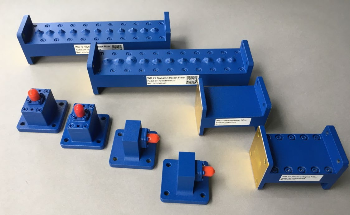
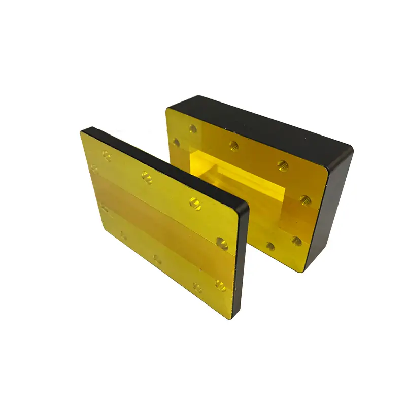
Special Waveguide Transitions
Special waveguide transitions are custom-engineered components used to connect different waveguide sizes, shapes, or types where direct mating is not possible. Dolph’s published range covers WR-2300 to WR-12 and 0.35 to 91.9 GHz, with VSWR ≤ 1.04:1 in overlapping bands. Available in Aluminum 6061 or Brass with UG, CPRG, and UBR flange options, they are built for precise interface matching in telecommunications, radar, satellite, and laboratory microwave systems.
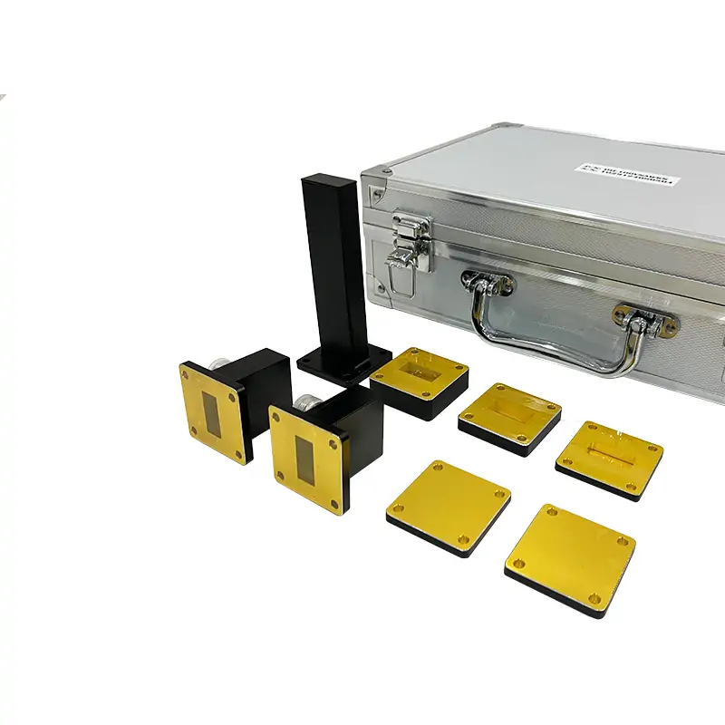
The Dolph Special Waveguide Transitions product family is engineered for interface adaptation between different waveguide sizes, shapes, or types across a published operating range of 0.35 to 91.9 GHz. Covering WR-2300 to WR-12, these transitions are built for microwave assemblies that require controlled geometry, stable interface matching, and low reflection performance. The published electrical target is VSWR ≤ 1.04:1 in overlapping bands, with available base materials including Aluminum 6061 and Brass. Supported flange configurations include UG, CPRG, and UBR, while external non-mating surfaces are finished in gray epoxy enamel for added environmental durability.
Configuration Scope
- Waveguide Coverage: WR-2300 to WR-12.
- Frequency Range: 0.35 to 91.9 GHz.
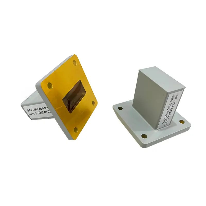
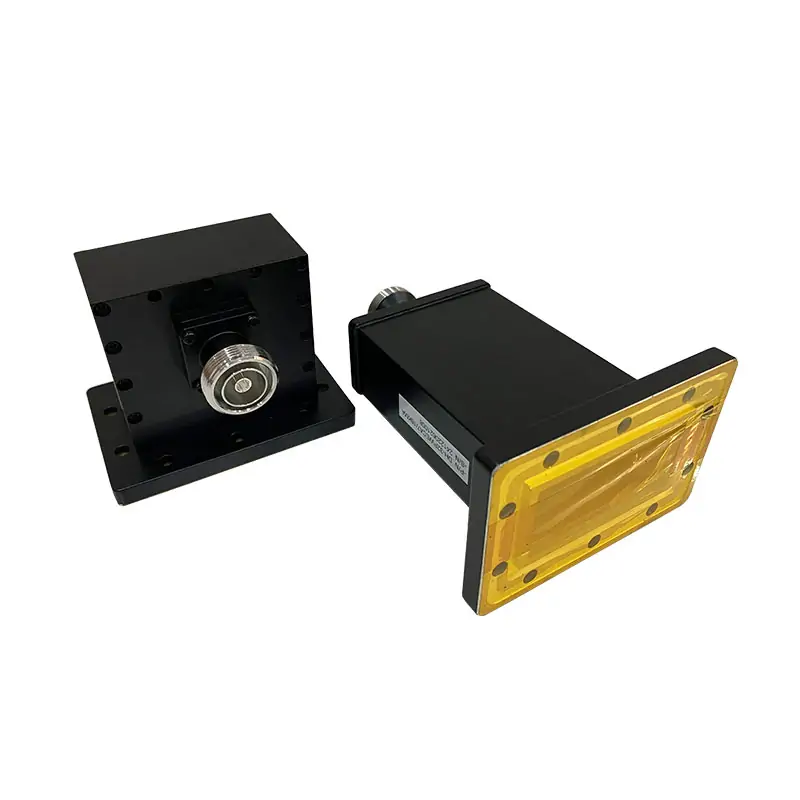
- Transition Purpose: Adaptation between different waveguide sizes, shapes, or interface types.
- Electrical Target: VSWR ≤ 1.04:1 in overlapping bands.
Interface & Materials
- Base Materials: Aluminum 6061 or Brass.
- Flange Options: UG, CPRG, UBR.
- Surface Finish: Gray epoxy enamel on external non-mating surfaces.
- Interface Matching: Suitable for assemblies requiring non-identical mating sections.
Standards & Commercial Data
- Flange Reference: Compatible with published UG / CPRG / UBR configurations.
- Naming Reference: Flange designation can be aligned with IEC / EIA reference systems.
- Website Marks: RoHS and ISO shown on the website.
- Warranty: 1-year warranty shown on the website.
Technical Data
| Category | Specification |
|---|---|
| Product Type | Special Waveguide Transitions |
| Waveguide Size Range | WR-2300 to WR-12 |
| Frequency Range | 0.35 to 91.9 GHz |
| VSWR | ≤ 1.04:1 in overlapping bands |
| Material | Aluminum 6061 or Brass |
| Flange Configuration | UG, CPRG, UBR |
| External Finish | Gray epoxy enamel (external, non-mating surfaces) |
RFQ Inputs
- Input Side: Waveguide size and flange type.
- Output Side: Waveguide size and flange type.
- Band Data: Operating range or overlap range.
- Material Choice: Aluminum 6061 or Brass.
- Drawing Support: Assembly drawing or space limit is recommended.
Application Fit
- Telecommunications: Interface adaptation inside microwave link assemblies.
- Radar Systems: Low-reflection transition section for mixed-interface builds.
- Satellite Communications: Broad size coverage for non-identical mating systems.
- Scientific Research: Useful for custom bench setups and non-standard RF routing.
Procurement Notes
- Interface Matching: Input and output flange data should be confirmed before order release.
- Mechanical Limits: Length or envelope restrictions should be provided at RFQ stage.
- Finish Scope: Published coating applies to external non-mating areas.
- Project Suitability: Final configuration should follow actual mating hardware requirements.
Customer Feedback
“We used this transition in a microwave assembly where the two sections were not a direct size match. The flange side was correct, the machining looked clean, and we did not need to touch up anything before installation.”
“Our main concern was getting the right input and output interface combination without delay. The unit arrived with the correct flange configuration, and that saved our team time during bench integration.”
“This was for a custom RF path where a standard same-size connection was not possible. The transition body looked solid, the external finish was even, and the assembly went together without unexpected fit issues.”
Technical FAQ
Q: Is this a standard catalog item or a custom transition family?
A: It is presented as a special transition family for adapting different waveguide sizes, shapes, or types. Final configuration should match the actual project interface.
Q: What waveguide range is published?
A: The published range is WR-2300 to WR-12, covering a broad span of microwave and millimeter-wave interface sizes.
Q: What frequency range is listed?
A: The published operating range is 0.35 to 91.9 GHz.
Q: What VSWR is shown on the page?
A: The published value is ≤ 1.04:1 in overlapping bands.
Q: Which flange options are available?
A: The page lists UG, CPRG, and UBR flange configurations.
Q: What should be included in the RFQ?
A: Include input and output waveguide sizes, flange types, operating band, material preference, and any drawing or space limitation if available.