
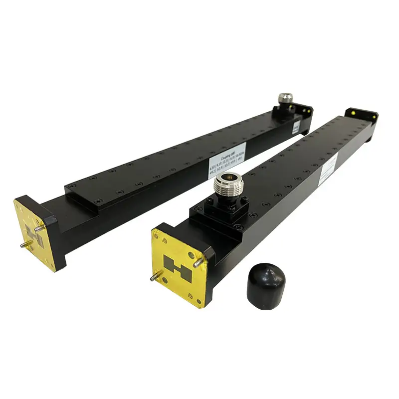
Waveguide Couplers
Dolph Microwave double-ridged waveguide couplers support fullband RF signal sampling across WRD84 to WRD180 waveguide systems, with model-specific frequency ranges from 0.84 GHz to 40.0 GHz. Available configurations include 10–60 dB coupling, 20–35 dB directivity, coupling accuracy of ±0.7 dB, frequency sensitivity of ±1 dB, single- or dual-directional coupling, and coaxial or flanged coupling interfaces.
Double-Ridged Waveguide Couplers
Dolph Microwave Waveguide Couplers are passive RF components used to extract a controlled portion of signal power from a double-ridged waveguide transmission path. The coupled output can be connected to monitoring, measurement, feedback, or signal-analysis equipment while the primary RF signal continues through the main waveguide path.
The product range covers WRD84 through WRD180 waveguide systems, with model-specific operating frequencies from 0.84 GHz to 40.0 GHz. Single- and dual-directional configurations are available with coaxial or flanged coupling interfaces and cover or grooved flange options.
Key Technical Specifications
| Parameter | Specification |
|---|---|
| Product Type | Double-ridged waveguide coupler |
| Waveguide Range | WRD84 to WRD180 |
| Frequency Coverage | 0.84–40.0 GHz, model dependent |
| Operating Bandwidth | Fullband |
| Coupling Range | 10–60 dB |
| Directivity | 20–35 dB |
| Coupling Accuracy | ±0.7 dB |
| Frequency Sensitivity | ±1 dB |
| Maximum VSWR | 1.08 or 1.1, depending on model |
| Directional Configuration | Single or dual |
| Coupling Interface | Coaxial or flange |
| Flange Type | Cover or grooved |
| Inside Finish | Iridite per MIL-C-5541 |
| Body Finish | Anticorrosion black painted |
Waveguide Coupler Model Range
Match the coupler to both the required operating frequency and the WRD waveguide size. Models with overlapping frequency ranges are not automatically interchangeable because the waveguide dimensions and mechanical interfaces differ.
| Model | WR Type | Frequency (GHz) | Bandwidth | VSWR Max. | Coupling (dB) | Directivity (dB) | Accuracy (dB) | Freq. Sensitivity (dB) |
|---|---|---|---|---|---|---|---|---|
| DH-84DRWC… | WRD84 | 0.84–2.0 | Fullband | 1.1 | 10–60 | 20–35 | ±0.7 | ±1 |
| DH-150DRWC… | WRD150 | 1.5–3.6 | Fullband | 1.1 | 10–60 | 20–35 | ±0.7 | ±1 |
| DH-200DRWC… | WRD200 | 2.0–4.8 | Fullband | 1.1 | 10–60 | 20–35 | ±0.7 | ±1 |
| DH-250DRWC… | WRD250 | 2.6–7.8 | Fullband | 1.1 | 10–60 | 20–35 | ±0.7 | ±1 |
| DH-350DRWC… | WRD350 | 3.5–8.2 | Fullband | 1.1 | 10–60 | 20–35 | ±0.7 | ±1 |
| DH-475DRWC… | WRD475 | 4.75–11.0 | Fullband | 1.08 | 10–60 | 20–35 | ±0.7 | ±1 |
| DH-500DRWC… | WRD500 | 5.0–18.0 | Fullband | 1.08 | 10–60 | 20–35 | ±0.7 | ±1 |
| DH-580DRWC… | WRD580 | 5.8–16.0 | Fullband | 1.08 | 10–60 | 20–35 | ±0.7 | ±1 |
| DH-650DRWC… | WRD650 | 6.5–18.0 | Fullband | 1.08 | 10–60 | 20–35 | ±0.7 | ±1 |
| DH-750DRWC… | WRD750 | 7.5–18.0 | Fullband | 1.08 | 10–60 | 20–35 | ±0.7 | ±1 |
| DH-700DRWC… | WRD700 | 7.0–18.0 | Fullband | 1.08 | 10–60 | 20–35 | ±0.7 | ±1 |
| DH-110DRWC… | WRD110 | 11.0–26.5 | Fullband | 1.08 | 10–60 | 20–35 | ±0.7 | ±1 |
| DH-180DRWC… | WRD180 | 18.0–40.0 | Fullband | 1.1 | 10–60 | 20–35 | ±0.7 | ±1 |
How to Select a Double-Ridged Waveguide Coupler
Match the WRD Waveguide Size
Start with the WRD size used by the existing waveguide assembly. Several models have overlapping operating bands, but different WRD sizes use different internal dimensions and flange interfaces. Frequency coverage alone is therefore not sufficient for model selection.
Select the Coupling Value
Available coupling values range from 10 dB to 60 dB. A lower numerical coupling value produces a higher sampled output, while a higher numerical coupling value extracts a smaller portion of the main-line RF signal. Select the value according to the main-line signal level and the input range of the connected monitoring or measurement equipment.
Choose Single or Dual Directional Coupling
A single-directional coupler is used when the system requires a sample in one propagation direction. A dual-directional configuration is appropriate when separate outputs are needed for forward and reverse signal monitoring.
- WC: Single Directional Coupler
- WDC: Dual Directional Coupler
- WHC: Single Loop Coupler
- WDHC: Dual Loop Coupler
Confirm the Coupling Interface and Flanges
The range supports coaxial or flanged coupling interfaces, together with cover or grooved main-line flange configurations. Specify the main waveguide flange and the coupled-output interface separately in the RFQ.
Engineering and Finish Considerations
Directional-coupler performance depends on the relationship between the main waveguide path and the coupling structure. Coupling level, directivity, accuracy, and frequency sensitivity should therefore be evaluated together when selecting a model.
The published coupling accuracy is ±0.7 dB and the frequency sensitivity is ±1 dB. The product specification also identifies an Iridite internal finish per MIL-C-5541 and an anticorrosion black-painted body finish.
Typical Applications
Double-ridged waveguide couplers provide a reduced-level signal output for monitoring, measurement, feedback, and signal-analysis functions in broadband RF and microwave systems.
- Forward-power monitoring in RF transmission paths
- Forward and reverse signal comparison
- Transmitter output monitoring
- RF measurement and test equipment
- Feedback and protection-system signal access
- Radar subsystem signal sampling
- Satellite communication equipment
- Broadband microwave laboratory and production testing
Manufacturing and Quality Management
Dolph Microwave manufacturing capabilities include CNC machining, turning, waveguide forming and bending, plating, soldering, brazing, and electroforming for waveguide components and customized microwave assemblies.
Dolph Microwave’s quality management system is certified to GB/T19001-2016/ISO9001:2015 for the design, manufacture, and sale of waveguide components.
Ordering Information
The following example shows how the main product configuration is represented in the part number:
DH-650DR WC 50 N K P A
| Code | Meaning |
|---|---|
| DH | Dolph Microwave |
| 650DR | WRD650 waveguide size |
| WC / WDC | Single or dual directional coupler |
| 50 | 50 dB coupling |
| N | Connector type |
| K | Female interface |
| P / M | Cover or grooved flange |
| A | Aluminum material |
Technical Downloads
Use the product datasheet to review the published model range and the flange-reference document to confirm the required double-ridged waveguide interface.
Frequently Asked Questions
What frequency range do these waveguide couplers cover?
The model range covers 0.84 GHz to 40.0 GHz across WRD84 through WRD180 double-ridged waveguide sizes. Each model is specified for fullband operation within its listed range.
How do I choose the correct WRD model?
Match the product to the WRD size of the existing waveguide assembly first, then verify that the required operating frequency falls within the model’s published range. Models with overlapping frequency ranges may use different mechanical interfaces.
What coupling values are available?
The product specification lists coupling values from 10 dB to 60 dB, with coupling accuracy of ±0.7 dB and frequency sensitivity of ±1 dB.
What is the difference between single and dual directional couplers?
A single-directional coupler provides a sampled output for one propagation direction. A dual-directional coupler is selected when separate outputs are required for forward and reverse monitoring.
Are coaxial and flanged coupling interfaces available?
Yes. The product specification lists coaxial and flanged coupling interfaces, together with cover and grooved main-line flange options.
Can the mechanical configuration be customized?
Standard and customized mechanical configurations are available. Include the WRD size, frequency range, coupling value, directional configuration, output interface, flange type, and installation constraints in the RFQ.
Related Waveguide Products
Compare a loop-coupled structure for double-ridged waveguide signal sampling.
For RF signal sampling in standard rectangular waveguide systems.
For installations that require a crossguide coupling configuration.
For probe-based RF signal sampling and monitoring.
For conversion between waveguide and coaxial transmission interfaces.
Request a Waveguide Coupler Quote
For model review and quotation, provide the required frequency range, WRD waveguide size, coupling value, single- or dual-directional configuration, coupling interface, flange arrangement, mechanical drawing, and expected quantity.
Submit Your RFQ






