
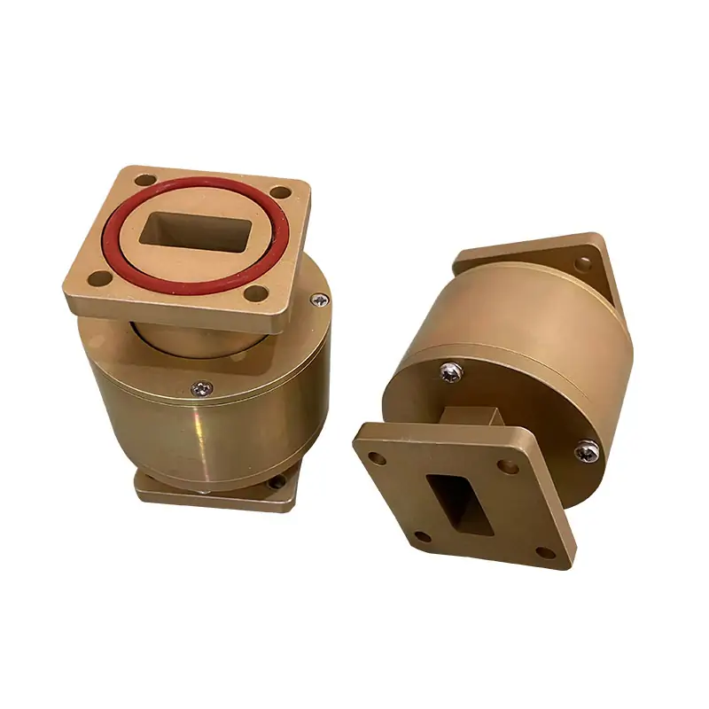
Waveguide Rotary Joint
A Waveguide Rotary Joint is a mechanical device that allows for the rotation of waveguide sections while maintaining a continuous transmission path for microwave signals. It is essential in systems requiring rotation of parts, such as radar antennas and satellite communication dishes, ensuring reliable signal transmission across rotating interfaces.
Match the rotating RF interface to the band, flange and power requirement
Dolph Microwave supplies single-channel waveguide rotary joints for transferring microwave energy from a stationary line to a rotating line. The published standard matrix covers 39 I-, L- and U-style models from 2.6 to 40 GHz, with custom RF and mechanical configurations available for project-specific interfaces.
WR284 end40 GHz
WR28 end
Keep the family-level ratings separate from model-table limits
The rotary-joint family is offered in U, L, I or F geometry from WR284 to WR28 and 2.6–40 GHz. The product specification example lists approximately 0.1 dB insertion loss and up to 600 kW peak power; model-specific values must still be checked against the standard matrix, PDF or project drawing.
Select the arm layout around the rotation axis
I-, L- and U-style models are listed in the standard matrix. F-style geometry is also available within the product family and should be confirmed against the required mechanical envelope.
In-line
Two in-line arms, both collinear with the axis of rotation.
Right-angle on one side
One arm is perpendicular to the axis of rotation.
Right-angle on both sides
Both arms are perpendicular to the axis of rotation.
Have the operating band and waveguide size?
Send the frequency range, waveguide size, I/L/U/F geometry, two flange interfaces, average/peak power and available installation envelope. We can check the nearest standard model or review a custom build.
Keep the full model data in the selection step
Match frequency, VSWR, insertion loss, average power, flange designation, IP rating, material and finish before moving to a drawing review.
| MODEL | FREQ RANGE (GHz) | OPERATING BW | VSWR (Max) | IL(dB) (Max) | AVG. POWER (W) | FLANGES TYPE | INGRESS PROTECTION | MATERIAL | FINISH | DATASHEET | |
|---|---|---|---|---|---|---|---|---|---|---|---|
| COVER | GROOVED | ||||||||||
| DH-32WRJI | 2.60-3.95 | 30% | 1.2:1 | 0.25 | 600 | UDR32 | PDR32 | IP65 | Al/Cu | Chromate/Painted | DWGSTEP |
| DH-32WRJL | 2.60-3.95 | 30% | 1.2 | 0.25 | 600 | UDR32 | PDR32 | IP65 | Al/Cu | Chromate/Painted | DWGSTEP |
| DH-32WRJU | 2.60-3.95 | 30% | 1.2 | 0.25 | 600 | UDR32 | PDR32 | IP65 | Al/Cu | Chromate/Painted | DWGSTEP |
| DH-40WRJI | 3.22-4.90 | 30% | 1.2 | 0.25 | 600 | UDR40 | PDR40 | IP65 | Al/Cu | Chromate/Painted | DWGSTEP |
| DH-40WRJL | 3.22-4.90 | 30% | 1.2 | 0.25 | 600 | UDR40 | PDR40 | IP65 | Al/Cu | Chromate/Painted | DWGSTEP |
| DH-40WRJU | 3.22-4.90 | 30% | 1.2 | 0.25 | 600 | UDR40 | PDR40 | IP65 | Al/Cu | Chromate/Painted | DWGSTEP |
| DH-48WRJI | 3.94-5.99 | 30% | 1.2 | 0.25 | 600 | UDR48 | PDR348 | IP65 | Al/Cu | Chromate/Painted | DWGSTEP |
| DH-48WRJL | 3.94-5.99 | 30% | 1.2 | 0.25 | 600 | UDR48 | PDR348 | IP65 | Al/Cu | Chromate/Painted | DWGSTEP |
| DH-48WRJU | 3.94-5.99 | 30% | 1.2 | 0.25 | 600 | UDR48 | PDR348 | IP65 | Al/Cu | Chromate/Painted | DWGSTEP |
| DH-58WRJI | 4.64-7.05 | 30% | 1.25 | 0.25 | 500 | UDR58 | PDR58 | IP65 | Al/Cu | Chromate/Painted | DWGSTEP |
| DH-58WRJL | 4.64-7.05 | 30% | 1.25 | 0.25 | 500 | UDR58 | PDR58 | IP65 | Al/Cu | Chromate/Painted | DWGSTEP |
| DH-58WRJU | 4.64-7.05 | 30% | 1.25 | 0.25 | 500 | UDR58 | PDR58 | IP65 | Al/Cu | Chromate/Painted | DWGSTEP |
| DH-70WRJI | 5.38-8.17 | 30% | 1.25 | 0.25 | 500 | UDR70 | PDR70 | IP65 | Al/Cu | Chromate/Painted | DWGSTEP |
| DH-70WRJL | 5.38-8.17 | 30% | 1.25 | 0.25 | 500 | UDR70 | PDR70 | IP65 | Al/Cu | Chromate/Painted | DWGSTEP |
| DH-70WRJU | 5.38-8.17 | 30% | 1.25 | 0.25 | 500 | UDR70 | PDR70 | IP65 | Al/Cu | Chromate/Painted | DWGSTEP |
| DH-84WRJI | 6.57-9.99 | 30% | 1.2 | 0.3 | 400 | UDR84/UBR84 | PDR84/PBR84 | IP65 | Al/Cu | Chromate/Painted | DWGSTEP |
| DH-84WRJL | 6.57-9.99 | 30% | 1.2 | 0.3 | 400 | UDR84/UBR84 | PDR84/PBR84 | IP65 | Al/Cu | Chromate/Painted | DWGSTEP |
| DH-84WRJU | 6.57-9.99 | 30% | 1.2 | 0.3 | 400 | UDR84/UBR84 | PDR84/PBR84 | IP65 | Al/Cu | Chromate/Painted | DWGSTEP |
| DH-100WRJI | 8.20-12.4 | 30% | 1.2 | 0.3 | 400 | UDR100/UBR100 | PDR100/PBR100 | IP65 | Al/Cu | Chromate/Painted | DWGSTEP |
| DH-100WRJL | 8.20-12.4 | 30% | 1.2 | 0.3 | 400 | UDR100/UBR100 | PDR100/PBR100 | IP65 | Al/Cu | Chromate/Painted | DWGSTEP |
| DH-100WRJU | 8.20-12.4 | 30% | 1.2 | 0.3 | 400 | UDR100/UBR100 | PDR100/PBR100 | IP65 | Al/Cu | Chromate/Painted | DWGSTEP |
| DH-120WRJI | 9.84-15.0 | 30% | 1.25 | 0.3 | 200 | UBR120 | PBR120 | IP65 | Al/Cu | Chromate/Painted | DWGSTEP |
| DH-120WRJL | 9.84-15.0 | 30% | 1.25 | 0.3 | 200 | UBR120 | PBR120 | IP65 | Al/Cu | Chromate/Painted | DWGSTEP |
| DH-120WRJU | 9.84-15.0 | 30% | 1.25 | 0.3 | 200 | UBR120 | PBR120 | IP65 | Al/Cu | Chromate/Painted | DWGSTEP |
| DH-140WRJI | 11.9-18.0 | 30% | 1.3 | 0.3 | 100 | UBR140 | PBR140 | IP65 | Al/Cu | Chromate/Painted | DWGSTEP |
| DH-140WRJL | 11.9-18.0 | 30% | 1.3 | 0.3 | 100 | UBR140 | PBR140 | IP65 | Al/Cu | Chromate/Painted | DWGSTEP |
| DH-140WRJU | 11.9-18.0 | 30% | 1.3 | 0.3 | 100 | UBR140 | PBR140 | IP65 | Al/Cu | Chromate/Painted | DWGSTEP |
| DH-180WRJI | 14.5-22.0 | 30% | 1.3 | 0.3 | 100 | UBR180 | PBR180 | IP65 | Al/Cu | Chromate/Painted | DWGSTEP |
| DH-180WRJL | 14.5-22.0 | 30% | 1.3 | 0.3 | 100 | UBR180 | PBR180 | IP65 | Al/Cu | Chromate/Painted | DWGSTEP |
| DH-180WRJU | 14.5-22.0 | 30% | 1.3 | 0.3 | 100 | UBR180 | PBR180 | IP65 | Al/Cu | Chromate/Painted | DWGSTEP |
| DH-220WRJI | 17.6-26.7 | 30% | 1.4 | 0.5 | 50 | UBR220 | PBR220 | IP65 | Al/Cu | Chromate/Painted | DWGSTEP |
| DH-220WRJL | 17.6-26.7 | 30% | 1.4 | 0.5 | 50 | UBR220 | PBR220 | IP65 | Al/Cu | Chromate/Painted | DWGSTEP |
| DH-220WRJU | 17.6-26.7 | 30% | 1.4 | 0.5 | 50 | UBR220 | PBR220 | IP65 | Al/Cu | Chromate/Painted | DWGSTEP |
| DH-260WRJI | 21.7-33.0 | 30% | 1.4 | 0.5 | 30 | UBR260 | PBR260 | IP65 | Al/Cu | Chromate/Painted | DWGSTEP |
| DH-260WRJL | 21.7-33.0 | 30% | 1.4 | 0.5 | 30 | UBR260 | PBR260 | IP65 | Al/Cu | Chromate/Painted | DWGSTEP |
| DH-260WRJU | 21.7-33.0 | 30% | 1.4 | 0.5 | 30 | UBR260 | PBR260 | IP65 | Al/Cu | Chromate/Painted | DWGSTEP |
| DH-320WRJI | 26.3-40.0 | 30% | 1.4 | 0.5 | 30 | UBR320 | PBR320 | IP65 | Al/Cu | Chromate/Painted | DWGSTEP |
| DH-320WRJL | 26.3-40.0 | 30% | 1.4 | 0.5 | 30 | UBR320 | PBR320 | IP65 | Al/Cu | Chromate/Painted | DWGSTEP |
| DH-320WRJU | 26.3-40.0 | 30% | 1.4 | 0.5 | 30 | UBR320 | PBR320 | IP65 | Al/Cu | Chromate/Painted | DWGSTEP |
Mobile: swipe horizontally to view every specification column.
Use the model matrix, RF sheet and flange sheet together
The downloadable rotary-joint PDF adds single-channel dynamic RF data such as VSWR WOW and insertion-loss WOW, plus IEC/EIA waveguide references and ordering information. The flange document maps standard waveguide sizes to Dolph flange designations.
Read the configuration from the part number
Part Number Guide: DH-100WRJI/L/UPMA400
100Waveguide SizeWR90WRJWaveguide TypeWaveguide Rotating JointI/L/UJoint StyleI, L, U-ShapePFlange TypeRectangular FlatMFlange TypeRectangular GroovedA/CMaterialAluminium, Cu400Power Rating400 W CWSend the details that control the final build
A short RFQ with the right inputs is more useful than a general application description. Attach an existing drawing when the rotary joint has to fit a fixed mechanical envelope.
Move to a more specific build when the standard matrix is not the final answer
Specific 10.7–14.5 GHz single-channel example with 1.2:1 max VSWR, 0.2 dB max insertion loss, 5 kW peak and 750 W CW.
→ High Power Waveguide Rotating JointUse this product family when the required CW/peak power is above the standard rotary-joint matrix.
→ WR28 Dual-Channel Rotary Joint ExampleA Ka-band SOTM project example for a two-channel rotating RF architecture.
→RF review backed by waveguide manufacturing capability
Dolph Microwave was founded in 2001. Its published manufacturing capabilities include CNC machining, turning, waveguide forming and bending, brazing/assembly, passivation/anodising and plating processes.
Send the band, waveguide, flanges and power requirement
We can compare your requirement with the 39 standard entries, check the flange interface and review whether the project needs a standard, high-power, dual-channel or custom rotary-joint configuration.







