

6.2 / 7.3 Meter Dual-Reflector Earth Station Antenna
Large-aperture fixed earth station antenna for Ku-band transmit and receive, with 6.2 m and 7.3 m reflector options, ring-focus optics, an elevation-over-azimuth kingpost pedestal, manual or motorized jack-screw drive, and field-changeable feed configurations. Published Ku-band RF data covers 10.95–12.75 GHz receive and 13.75–14.5 GHz transmit.
The model datasheets also state X- (Military/WGS), C- and Ka-band capabilities. For a non-Ku configuration, confirm the required frequency range, polarization, ports and feed interface before quotation.
Choose the aperture from the published RF requirement
Both models use the same basic mechanical platform concept. The 7.3 m model provides the higher published Ku-band mid-band gain and the narrower published 3 dB beam width; the 6.2 m model keeps the same 0.5 mm RMS surface accuracy and the same listed Ku-band feed interface.
Published Product Configuration
| Parameter | 6.2 Meter Specifications | 7.3 Meter Specifications |
|---|---|---|
| Frequency Band | Ku-band | Ku-band |
| Reflector Design | Dual-Reflector | Dual-Reflector |
| Pedestal Type | EL. over Az. LMA | EL. over Az. LMA |
| Wind Survival | 125 Mph Standard, 180 Mph High Wind Option | 125 Mph Standard, 180 Mph High Wind Option |
| Feed System | Wide-band LP/CP switchable, Field Changeable | Wide-band LP/CP switchable, Field Changeable |
| Construction | Galvanized Steel, Hot-Dipped Option | Galvanized Steel, Hot-Dipped Option |
| Operational Options | Manual, Motorized | Manual, Motorized |
Product Page Key Features
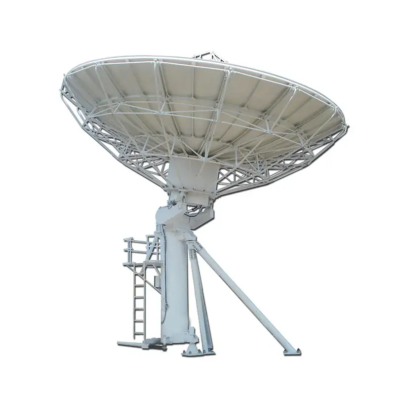
6.2 Meter RF & Antenna Specifications
Type: DH 6.2 Meter DR Ku-band Antenna Capability line: X- (Military/WGS), C-, or Ka-Band Capabilities
The 6.2 Meter Dual-Reflector Earth Station Antenna reflector incorporates stretch-formed doubly contoured panels with matched radials and hub for ease of field alignment. The standard elevation-over-azimuth LMA pedestal is described for high stiffness and stability, full orbital arc coverage and fine drive performance, and for the pointing accuracy required for Ku-band operation. The datasheet description states that RF specifications can meet FCC 25.209, IESS and ITU-RS.580-5, INMARSAT, ASIASAT, INTELSAT, APT and Chinasat, etc.
| Ku-band Linear | Receive | Transmit |
|---|---|---|
| Frequency, GHz | 10.95-12.75 | 13.75-14.5 |
| Mid-Band Gain, dBi | 56.18 | 57.11 |
| VSWR | 1.3:1 | 1.3:1 |
| 3dB Beam Width, deg | 0.26 | 0.23 |
| Noise Temperature, 10 Deg Elevation, K | 56 | |
| Noise Temperature, 20 Deg Elevation, K | 42 | |
| Typical G/T @ 10 Degrees | 34.8 | |
| Port to Port Isolation, Tx to Rx (same band), dB | 85 | |
| Tx Power Capability, KW | 1 | |
| Cross-pol. on Axis, dB | 35 | 35 |
| Insertion Loss, dB | 0.30 | 0.25 |
| Feed Interface | WR-75 CPR | WR-75 CPR |
| Radiation Pattern Compliance | FCC 25.209, ITU-RS.580-6 | |
| First sidelobe, dB | ≤ -14 | |
| Sidelobe Envelope | 32 – 25 log (1°≤θ<20°) | |
6.2 Meter Mechanical & Environmental Specifications
| Antenna Optics | Ring- focus design |
| Refector Aperture | 6.2 Meters (20.3 Feet) |
| Reflector Panels | 16 precision-formed aluminum panels |
| Antenna Foundation | Reinforced Concrete Foundation, or Non-penetrating mount (NPM) |
| Mount Configuration | Kingpost Pedestal Elevation-over Azimuth axis configuration |
| Drive Type | Manual / Motorized jack screw |
| Surface Accuracy (RMS) | 0.5 mm |
| Finishes — Reflector Surface | Aluminum panels with high-diffusing white paint |
| Pedestal & Reflector Backup Structure | Galvanized steel parts/ Hot Dipped Galvanized After Fabrication Galvanized |
| Elevation Travel | 5° to 90 ° Continuous, |
| Azimuth Travel | ±85° or 360° Continuous, |
| Pol. Travel | ±90°Continuous, |
| Operational Wind | 45 mph (72 km/h) gusting to 60 mph (97 km/h) |
| Survival Wind | 125 mph (200 km/h), |
| Temperature | -40° C to +50° C |
| Humidity | 0-98% |
7.3 Meter RF & Antenna Specifications
Type: DH 7.3 Meter DR Ku-band Antenna Capability line: X- (Military/WGS), C-, or Ka-Band Capabilities
The 7.3 Meter Dual-Reflector Earth Station Antenna reflector incorporates stretch-formed doubly contoured panels with matched radials and hub for ease of field alignment. The standard elevation-over-azimuth LMA pedestal is described for high stiffness and stability, full orbital arc coverage and fine drive performance, and for the pointing accuracy required for Ku-band operation. The datasheet description states that RF specifications can meet FCC 25.209, IESS and ITU-RS.580-5, INMARSAT, ASIASAT, INTELSAT, APT and Chinasat, etc.
| Ku-band Linear | Receive | Transmit |
|---|---|---|
| Frequency, GHz | 10.95-12.75 | 13.75-14.5 |
| Mid-Band Gain, dBi | 57.6 | 58.53 |
| VSWR | 1.3:1 | 1.3:1 |
| 3dB Beam Width, deg | 0.22 | 0.19 |
| Noise Temperature, 10 Deg Elevation, K | 73 | |
| Noise Temperature, 20 Deg Elevation, K | 65 | |
| Typical G/T @ 10 Degrees | 36.1 | |
| Ports | 2/4 | |
| Port to Port Isolation, Tx to Rx (same band), dB | 85 | |
| Tx Power Capability, KW | 1 | |
| Cross-pol. on Axis, dB | 35 | 35 |
| Insertion Loss, dB | 0.30 | 0.25 |
| Feed Interface | WR-75 CPR | WR-75 CPR |
| Radiation Pattern Compliance | FCC 25.209, ITU-RS.580-6 | |
| First sidelobe, dB | ≤ -14 | |
| Sidelobe Envelope | 32 – 25 log (1°≤θ<20°) | |
7.3 Meter Mechanical & Environmental Specifications
| Antenna Optics | Ring- focus design |
| Refector Aperture | 7.3 Meters (23.9 Feet) |
| Reflector Panels | 16 precision-formed aluminum panels |
| Antenna Foundation | Reinforced Concrete Foundation, or Non-penetrating mount (NPM) |
| Mount Configuration | Kingpost Pedestal Elevation-over Azimuth axis configuration |
| Drive Type | Manual / Motorized jack screw |
| Surface Accuracy (RMS) | 0.5 mm |
| Finishes — Reflector Surface | Aluminum panels with high-diffusing white paint |
| Pedestal & Reflector Backup Structure | Galvanized steel parts/ Hot Dipped Galvanized After Fabrication Galvanized |
| Elevation Travel | 5° to 90 ° Continuous, |
| Azimuth Travel | ±85° or 360° Continuous, |
| Pol. Travel | ±90°Continuous, |
| Operational Wind | 45 mph (72 km/h) gusting to 60 mph (97 km/h) |
| Survival Wind | 125 mph (200 km/h), |
| Temperature | -40° C to +50° C |
| Humidity | 0-98% |
Published Datasheet Key Features — 6.2 Meter
Published Datasheet Key Features — 7.3 Meter
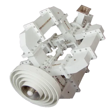
Feed configuration is part of the antenna selection
The Ku-band datasheet feed interface is WR-75 CPR. For X-, C- or Ka-band work, the datasheets state that different frequency ranges are available from different feed configurations, so the feed must be specified with the antenna rather than assumed from the Ku-band table.
Dolph’s custom antenna feed systems cover single-, dual- and triple-band arrangements using feed horns, OMTs, filters, diplexers, polarizers and rotary joints. See the antenna feeder networks when the RF path needs to be reviewed as a complete assembly.
For multi-band planning, the engineering article How to integrate multiple frequency bands in antenna feed network covers the feed-network selection and integration points.
Ask About Feed ConfigurationWhere this antenna is listed for use
The current product page lists the following application areas. Final suitability depends on the required frequency plan, link budget, feed, pointing arrangement and site conditions.


Engineering, feed manufacture and test support
Dolph Microwave was founded in 2001. Its published manufacturing scope includes CNC machining, turning, waveguide forming and bending, brazing and assembly. The laboratory capability page lists RF vector and scalar measurement systems up to 100 GHz, antenna anechoic chambers, high-power transmitters and environmental testing for temperature, altitude, salt fog and humidity.
For complete antenna projects, Dolph’s company information states that system integration can combine its own microwave parts and feed systems with antennas from reflector suppliers. This distinction is important when defining responsibility for the reflector, feed, RF path and project documentation.
Review manufacturing and test capabilities and company information before supplier qualification. The website also publishes ISO 9001:2015 quality-system documentation for waveguide component design, manufacture and sale; request the current certificate revision when your procurement process requires it.
What to send for configuration review
A useful RFQ can be short. These inputs are enough to separate the antenna size, feed and mechanical options that need confirmation.
If 6.2 / 7.3 m is not the right platform
Use a different antenna platform when the aperture, orbit type or installation format changes.
Review the 3.7 / 4.5 Meter Dual-Reflector Earth Station Antenna when the project does not need a 6.2 m or 7.3 m aperture.
For general size selection, see What is the size of earth station antenna.
Review the 9.0 Meter Earth Station Antenna or 11.3 Meter Earth Station Antenna when the link design calls for a larger reflector.
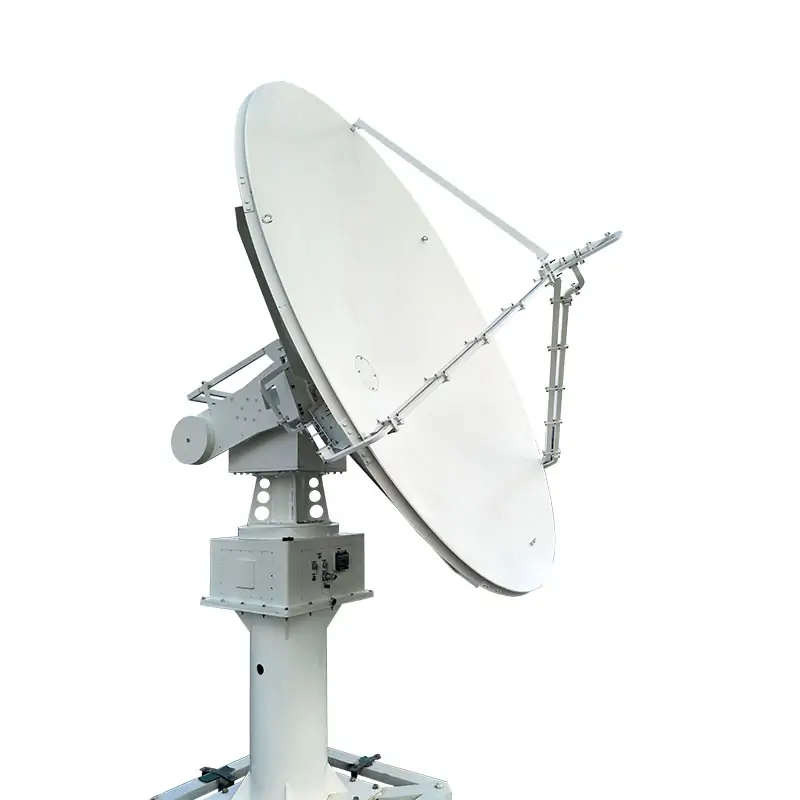 Tracking instead of fixed pointing
Use the Low / Medium Earth Orbit Satellite Tracking Antenna when the requirement is LEO/MEO tracking rather than a fixed earth-station pointing arrangement.
Documentation and supplier support
The product datasheets provide the RF, mechanical and environmental values used on this page. The company support page states a one-year warranty from delivery for defective material and workmanship, with replacement of defective parts and repair work required by normal use during that period.
For vendor qualification and production background, review About Dolph Microwave, Manufacturing and the Support and Warranty page.
Send the RF requirement before you lock the antenna size
Include band, polarization, Tx/Rx frequencies, site wind, foundation, drive preference and quantity. The 6.2 m or 7.3 m configuration can then be matched to the published RF and mechanical data.







