
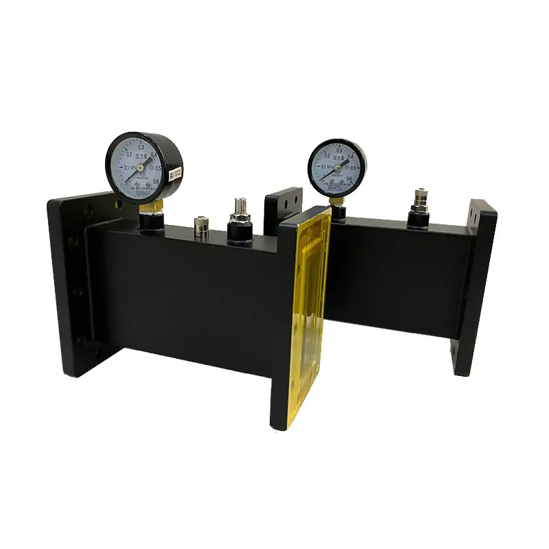
Waveguide Pressure Inlets Section
Waveguide pressure inlets are specialized sections designed for the controlled introduction of gases into waveguide systems. These components are crucial for maintaining desired atmospheric conditions within waveguides, supporting accurate signal transmission and preventing moisture ingress in applications such as radar, telecommunications, and satellite communications.
PRESSURIZED WAVEGUIDE HARDWARE
Waveguide Pressure Inlet Sections
Dolph Microwave pressure inlet sections introduce air or other gases into a waveguide line while supporting controlled internal pressure. Configurations are available with or without a pressure gauge, with cover, grooved or choke flange options, and with standard or customized mechanical configurations for the selected waveguide system.
CONFIGURATION SUPPORT
Match the inlet section to your waveguide line
Send the operating band and waveguide size together with the required pressure, inlet connection, valve, length, flange style, material and gauge requirement. Dolph Microwave can then match a published configuration or discuss a customized mechanical configuration for the application.
Waveguide & band
Start with the WR size and operating frequency range so the mechanical section matches the line.
Pressure & monitoring
Select the required pressure range and whether an integrated pressure gauge is needed.
Inlet, valve & length
Published models show 1/8-27 NPTF, Schrader valves and 19 / 108 / 152 mm length options.
Flange & material
Choose the applicable cover, grooved or choke flange configuration and confirm the material/finish for the selected model.
PRODUCT PAGE DATA
Model specifications
The following model data is retained from the current product page. “DWG” and “STEP” are shown exactly as the available datasheet formats on that page.
| MODEL | FREQ. RANGE (GHz) | WG SIZE | VSWR | PRESSURE (PSIG) | INLET SIZE (CUSTOMIZABLE) | GAS VALVES | LENGTH (mm) | COVER | GROOVED | MATERIAL | DATASHEET |
|---|---|---|---|---|---|---|---|---|---|---|---|
| DH-14WPISV… | 1.13-1.73 | WR650 | 1.05:1 | 45 | 1/8-27 NPTF | Schrader Valves | 19, 108,152 | UDR14 | PDR14 | AI | DWG / STEP |
| DH-18WPISV… | 1.45-2.2 | WR510 | 1.05:1 | 45 | 1/8-27 NPTF | Schrader Valves | 19, 108,152 | UDR18 | PDR18 | AI | DWG / STEP |
| DH-22WPISV… | 1.72-2.61 | WR430 | 1.05:1 | 45 | 1/8-27 NPTF | Schrader Valves | 19, 108,152 | UDR22 | PDR22 | AI | DWG / STEP |
| DH-26WPISV… | 2.17-3.3 | WR340 | 1.05:1 | 45 | 1/8-27 NPTF | Schrader Valves | 19, 108,152 | UDR26 | PDR26 | AI | DWG / STEP |
| DH-32WPISV… | 2.6-3.95 | WR284 | 1.05:1 | 45 | 1/8-27 NPTF | Schrader Valves | 19, 108,152 | UDR32 | PDR32 | AI | DWG / STEP |
| DH-40WPISV… | 3.22-4.9 | WR229 | 1.05:1 | 45 | 1/8-27 NPTF | Schrader Valves | 19, 108,152 | UDR40 | PDR40 | AI | DWG / STEP |
| DH-48WPISV… | 3.94-5.99 | WR187 | 1.05:1 | 45 | 1/8-27 NPTF | Schrader Valves | 19, 108,152 | UDR48 | PDR348 | AI | DWG / STEP |
| DH-58WPISV… | 4.64-7.05 | WR159 | 1.05:1 | 45 | 1/8-27 NPTF | Schrader Valves | 19, 108,152 | UDR58 | PDR58 | AI | DWG / STEP |
| DH-70WPISV… | 5.38-8.17 | WR137 | 1.05:1 | 45 | 1/8-27 NPTF | Schrader Valves | 19, 108,152 | UDR70 | PDR70 | AI | DWG / STEP |
| DH-84WPISV… | 6.57-9.99 | WR112 | 1.05:1 | 45 | 1/8-27 NPTF | Schrader Valves | 19, 108,152 | UDR84/UBR84 | PDR84/PBR84 | AI | DWG / STEP |
| DH-100WPISV… | 8.2-12.5 | WR90 | 1.05:1 | 45 | 1/8-27 NPTF | Schrader Valves | 19, 108,152 | UDR100/UBR100 | PDR100/PBR100 | AI | DWG / STEP |
| DH-120WPISV… | 9.84-15 | WR75 | 1.05:1 | 45 | 1/8-27 NPTF | Schrader Valves | 19, 108,152 | UBR120 | PBR120 | AI | DWG / STEP |
| DH-140WPISV… | 11.9-18 | WR62 | 1.05:1 | 45 | 1/8-27 NPTF | Schrader Valves | 19, 108,152 | UBR140 | PBR140 | AI | DWG / STEP |
| DH-180WPISV… | 14.5-22 | WR51 | 1.05:1 | 45 | 1/8-27 NPTF | Schrader Valves | 19, 108,152 | UBR180 | PBR180 | AI | DWG / STEP |
| DH-220WPISV… | 17.6-26.7 | WR42 | 1.05:1 | 45 | 1/8-27 NPTF | Schrader Valves | 19, 108,152 | UBR220 | PBR220 | Al/Cu | DWG / STEP |
| DH-260WPISV… | 21.7-33 | WR34 | 1.05:1 | 45 | 1/8-27 NPTF | Schrader Valves | 19, 108,152 | UBR260 | PBR260 | Al/Cu | DWG / STEP |
| DH-320WPISV… | 26.3-40 | WR28 | 1.05:1 | 45 | 1/8-27 NPTF | Schrader Valves | 19, 108,152 | UBR320 | PBR320 | Al/Cu | DWG / STEP |
Configuration note: the live product table and the linked product brochure publish different pressure, dimensional and material fields for some configurations. Confirm the selected model/drawing and final ordered values with Dolph Microwave before placing the order.
OFFICIAL PRODUCT BROCHURE
Brochure specification reference
The one-page product brochure linked from this product page extends the model reference through WR10 and shows pressure as a range by model group. These values are retained separately rather than merged into the live-page table.
| Model | WR Type | Frequency (GHz) | VSWR Max. | Thickness (mm) | Pressure (PSIG) |
|---|---|---|---|---|---|
| DH-14WPI… | WR650 | 1.13-1.73 | 1.05 | 50 | 15-45 |
| DH-18WPI… | WR510 | 1.45-2.20 | 1.05 | 50 | 15-45 |
| DH-22WPI… | WR430 | 1.72-2.61 | 1.05 | 19 | 15-45 |
| DH-26WPI… | WR340 | 2.17-3.30 | 1.05 | 19 | 15-45 |
| DH-32WPI… | WR284 | 2.60-3.95 | 1.05 | 19 | 15-45 |
| DH-40WPI… | WR229 | 3.22-4.9 | 1.05 | 19 | 15-45 |
| DH-48WPI… | WR187 | 3.94-5.99 | 1.05 | 19 | 15-45 |
| DH-58WPI… | WR159 | 4.64-7.05 | 1.05 | 19 | 15-45 |
| DH-70WPI… | WR137 | 5.38-8.17 | 1.05 | 19 | 15-45 |
| DH-84WPI… | WR112 | 6.57-9.99 | 1.05 | 19 | 15-45 |
| DH-100WPI… | WR90 | 8.20-12.40 | 1.05 | 19 | 15-45 |
| DH-120WPI… | WR75 | 9.84-15.0 | 1.05 | 19 | 15-45 |
| DH-140WPI… | WR62 | 11.9-18.0 | 1.05 | 19 | 15-45 |
| DH-180WPI… | WR51 | 14.5-22.0 | 1.05 | 19 | 15-45 |
| DH-220WPI… | WR42 | 17.6-26.7 | 1.05 | 19 | 15-45 |
| DH-260WPI… | WR34 | 21.7-33.0 | 1.05 | 19 | 15-45 |
| DH-320WPI… | WR28 | 26.3-40.0 | 1.05 | 19 | 15-45 |
| DH-400WPI… | WR22 | 33.0-50.0 | 1.05 | 19 | 15-20 |
| DH-500WPI… | WR19 | 40.0-60.0 | 1.05 | 19 | 15-20 |
| DH-620WPI… | WR15 | 55.0-65.0 | 1.05 | 19 | 15-20 |
| DH-740WPI… | WR12 | 60.5-91.9 | 1.05 | 19 | 15-20 |
| DH-900WPI… | WR10 | 73.8-112.0 | 1.05 | 19 | 15-20 |
Inlet / finish data shown in the brochure
| Inlet Size | Flange Type | Inside Finish | Body Finish | Material |
|---|---|---|---|---|
| 1/8-27 NPT | FUGP | Iridite per MIL-C-5541 | Anticorrosion Black Painted | Brass |
| 1/8-27 NPT | FUGP | Iridite per MIL-C-5541 | Anticorrosion Black Painted | Brass |
| 1/8-27 NPT | FUGP | Iridite per MIL-C-5541 | Anticorrosion Black Painted | Brass |
| 1/8-27 NPT | FUGP | Iridite per MIL-C-5541 | Anticorrosion Black Painted | Brass |
PART NUMBER GUIDE
Read the configuration code
Product-page example: DH-100WPISV152PMA
100Waveguide Size — WR90WPIWaveguide Type — Waveguide Pressure InletsSVSG152Waveguide Type — Pressurizing Section with Gauge and Schrader Valves, Length 152 mm108Length — 108 mm, Pressurizing Section with Schrader Valves19Length — 19 mm, Flange Spacer InletsPFlange Type — Rectangular FlatMFlange Type — Rectangular GroovedA/CMaterial — Aluminium, CuBROCHURE ORDERING INFORMATION
Example ordering sequence
Brochure example: DH – 120 WPI 19 P M A
DHDolph Microwave120WR75WPIPressure InletsWPISGInlets Section with Pressure Gauge19Thickiness 19 mmPFlange CoverMFlange GroovedAMaterial AlFINISH & MECHANICAL OPTIONS
Surface treatment and configuration details
WHY IT MATTERS IN THE LINE
Pressure access without changing the waveguide function
The inlet section provides a defined point for introducing air or another gas into the waveguide system. An optional gauge supports pressure monitoring, while the available flange and mechanical choices help the section fit the surrounding waveguide hardware.
APPLICATIONS
Where pressure inlet sections are used
Radar systems
Used where stable internal waveguide conditions are required for consistent RF transmission.
Telecommunications
Supports pressurized waveguide runs used in ground-based and satellite communication infrastructure.
Satellite communications
Provides a controlled pressure inlet point in waveguide assemblies used for signal transmission.
Scientific research
Suitable for laboratory waveguide setups that require controlled internal atmospheric conditions.
Aerospace
Used in pressurized waveguide arrangements where environmental control contributes to system reliability.
DOCUMENTATION & SUPPORT
Order against the selected model and drawing
For quotation, include the required WR size, frequency range, operating pressure, inlet size, gauge requirement, flange type, length and material. Where published data differs by source or configuration, use the final selected drawing and confirmed order specification.
REQUEST A CONFIGURATION
Send your waveguide and pressure requirements
Include the WR size, frequency, pressure, inlet connection, valve, length, flange, material and gauge requirement so the suitable pressure inlet section can be identified.







