
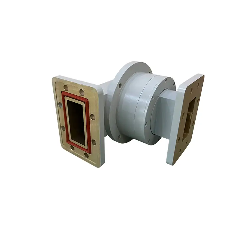
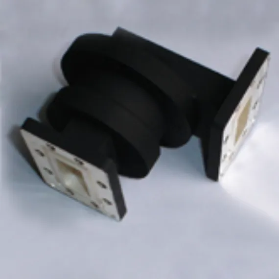
High-power rotary joints matched to the RF path
The standard family covers 1.72–40.0 GHz with 10% operating bandwidth. Published model ratings run from 300 W to 12,000 W average power, with maximum insertion loss of 0.2–0.25 dB and IP65 protection.
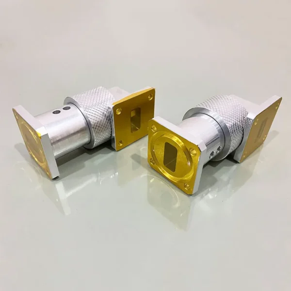
Send the values that determine the build
Frequency and waveguide size
Send the complete operating band and required waveguide size. The listed high-power models use 10% operating bandwidth.
Average and peak power
State CW or average power, peak power, pulse width and duty condition. Do not select from average power alone.
Joint geometry
Choose the required I-, L- or U-style routing around the rotation axis and provide the available installation envelope.
Both flange interfaces
Confirm cover or grooved construction and the exact mating designation on each side.
Environment
Standard rows list IP65. State any pressurization, sealing, temperature or finish requirement that must be reviewed.
Drawing or envelope
Send a drawing, sketch or dimensional limit when the catalog geometry does not fit the assembly.
Choose the arm layout around the rotation axis
I-, L- and U-style models are published across the standard matrix. Final geometry should be checked against the installation envelope and flange orientation.
In-line
Both waveguide arms remain collinear with the rotation axis.
Right-angle on one side
One arm turns perpendicular to the rotation axis.
Right-angle on both sides
Both arms are perpendicular to the rotation axis.
Need the nearest standard model before you issue an RFQ?
Send frequency range, waveguide size, I/L/U layout, both flanges, average/peak power and the available envelope.
Standard model matrix
All published model rows are retained below. On mobile, swipe horizontally to review every parameter.
| MODEL | FREQ RANGE (GHz) | OPERATING BW | VSWR (Max) | IL(dB) (Max) | AVG. POWER (W) | FLANGES TYPE | INGRESS PROTECTION | MATERIAL | FINISH | DATASHEET | ||
|---|---|---|---|---|---|---|---|---|---|---|---|---|
| COVER | GROOVED | STEP | ||||||||||
| DH-22WHPJI | 1.72-2.61 | 10% | 1.15:1 | 0.2 | 12000 | UDR32 | PDR32 | IP65 | Al/Cu | Chromate/Painted | STEP | |
| DH-22WHPJL | 1.72-2.61 | 10% | 1.15:1 | 0.2 | 12000 | UDR32 | PDR32 | IP65 | Al/Cu | Chromate/Painted | STEP | |
| DH-22WHPJU | 1.72-2.61 | 10% | 1.15:1 | 0.2 | 12000 | UDR32 | PDR32 | IP65 | Al/Cu | Chromate/Painted | STEP | |
| DH-32WHPJI | 2.60-3.95 | 10% | 1.15:1 | 0.2 | 10000 | UDR32 | PDR32 | IP65 | Al/Cu | Chromate/Painted | STEP | |
| DH-32WHPJL | 2.60-3.95 | 10% | 1.15:1 | 0.2 | 10000 | UDR32 | PDR32 | IP65 | Al/Cu | Chromate/Painted | STEP | |
| DH-32WHPJU | 2.60-3.95 | 10% | 1.15:1 | 0.2 | 10000 | UDR32 | PDR32 | IP65 | Al/Cu | Chromate/Painted | STEP | |
| DH-40WHPJI | 3.22-4.90 | 10% | 1.15:1 | 0.2 | 3000 | UDR40 | PDR40 | IP65 | Al/Cu | Chromate/Painted | STEP | |
| DH-40WHPJL | 3.22-4.90 | 10% | 1.15:1 | 0.2 | 3000 | UDR40 | PDR40 | IP65 | Al/Cu | Chromate/Painted | STEP | |
| DH-40WHPJU | 3.22-4.90 | 10% | 1.15:1 | 0.2 | 3000 | UDR40 | PDR40 | IP65 | Al/Cu | Chromate/Painted | STEP | |
| DH-48WHPJI | 3.94-5.99 | 10% | 1.15:1 | 0.2 | 3000 | UDR48 | PDR348 | IP65 | Al/Cu | Chromate/Painted | STEP | |
| DH-48WHPJL | 3.94-5.99 | 10% | 1.15:1 | 0.2 | 3000 | UDR48 | PDR348 | IP65 | Al/Cu | Chromate/Painted | STEP | |
| DH-48WHPJU | 3.94-5.99 | 10% | 1.15:1 | 0.2 | 3000 | UDR48 | PDR348 | IP65 | Al/Cu | Chromate/Painted | STEP | |
| DH-58WHPJI | 4.64-7.05 | 10% | 1.15:1 | 0.2 | 3000 | UDR58 | PDR58 | IP65 | Al/Cu | Chromate/Painted | STEP | |
| DH-58WHPJL | 4.64-7.05 | 10% | 1.15:1 | 0.2 | 3000 | UDR58 | PDR58 | IP65 | Al/Cu | Chromate/Painted | STEP | |
| DH-58WHPJU | 4.64-7.05 | 10% | 1.15:1 | 0.2 | 3000 | UDR58 | PDR58 | IP65 | Al/Cu | Chromate/Painted | STEP | |
| DH-70WHPJI | 5.38-8.17 | 10% | 1.15:1 | 0.2 | 2000 | UDR70 | PDR70 | IP65 | Al/Cu | Chromate/Painted | STEP | |
| DH-70WHPJL | 5.38-8.17 | 10% | 1.15:1 | 0.2 | 2000 | UDR70 | PDR70 | IP65 | Al/Cu | Chromate/Painted | STEP | |
| DH-70WHPJU | 5.38-8.17 | 10% | 1.15:1 | 0.2 | 2000 | UDR70 | PDR70 | IP65 | Al/Cu | Chromate/Painted | STEP | |
| DH-84WHPJI | 6.57-9.99 | 10% | 1.2:1 | 0.2 | 2000 | UDR84/UBR84 | PDR84/PBR84 | IP65 | Al/Cu | Chromate/Painted | STEP | |
| DH-84WHPJL | 6.57-9.99 | 10% | 1.2:1 | 0.2 | 2000 | UDR84/UBR84 | PDR84/PBR84 | IP65 | Al/Cu | Chromate/Painted | STEP | |
| DH-84WHPJU | 6.57-9.99 | 10% | 1.2:1 | 0.2 | 2000 | UDR84/UBR84 | PDR84/PBR84 | IP65 | Al/Cu | Chromate/Painted | STEP | |
| DH-100WHPJI | 8.20-12.4 | 10% | 1.2:1 | 0.2 | 2000 | UDR100/UBR100 | PDR100/PBR100 | IP65 | Al/Cu | Chromate/Painted | STEP | |
| DH-100WHPJL | 8.20-12.4 | 10% | 1.2:1 | 0.2 | 2000 | UDR100/UBR100 | PDR100/PBR100 | IP65 | Al/Cu | Chromate/Painted | STEP | |
| DH-100WHPJU | 8.20-12.4 | 10% | 1.2:1 | 0.2 | 2000 | UDR100/UBR100 | PDR100/PBR100 | IP65 | Al/Cu | Chromate/Painted | STEP | |
| DH-120WHPJI | 9.84-15.0 | 10% | 1.2:1 | 0.2 | 1000 | UBR120 | PBR120 | IP65 | Al/Cu | Chromate/Painted | STEP | |
| DH-120WHPJL | 9.84-15.0 | 10% | 1.2:1 | 0.2 | 1000 | UBR120 | PBR120 | IP65 | Al/Cu | Chromate/Painted | STEP | |
| DH-120WHPJU | 9.84-15.0 | 10% | 1.2:1 | 0.2 | 1000 | UBR120 | PBR120 | IP65 | Al/Cu | Chromate/Painted | STEP | |
| DH-140WHPJI | 11.9-18.0 | 10% | 1.25:1 | 0.2 | 2000 | UBR140 | PBR140 | IP65 | Al/Cu | Chromate/Painted | STEP | |
| DH-140WHPJL | 11.9-18.0 | 10% | 1.25:1 | 0.2 | 2000 | UBR140 | PBR140 | IP65 | Al/Cu | Chromate/Painted | STEP | |
| DH-140WHPJU | 11.9-18.0 | 10% | 1.25:1 | 0.2 | 2000 | UBR140 | PBR140 | IP65 | Al/Cu | Chromate/Painted | STEP | |
| DH-180WHPJI | 14.5-22.0 | 10% | 1.25:1 | 0.25 | 500 | UBR180 | PBR180 | IP65 | Al/Cu | Chromate/Painted | STEP | |
| DH-180WHPJL | 14.5-22.0 | 10% | 1.25:1 | 0.25 | 500 | UBR180 | PBR180 | IP65 | Al/Cu | Chromate/Painted | STEP | |
| DH-180WHPJU | 14.5-22.0 | 10% | 1.25:1 | 0.25 | 500 | UBR180 | PBR180 | IP65 | Al/Cu | Chromate/Painted | STEP | |
| DH-220WHPJI | 17.6-26.7 | 10% | 1.25:1 | 0.25 | 500 | UBR220 | PBR220 | IP65 | Al/Cu | Chromate/Painted | STEP | |
| DH-220WHPJL | 17.6-26.7 | 10% | 1.25:1 | 0.25 | 500 | UBR220 | PBR220 | IP65 | Al/Cu | Chromate/Painted | STEP | |
| DH-220WHPJU | 17.6-26.7 | 10% | 1.25:1 | 0.25 | 500 | UBR220 | PBR220 | IP65 | Al/Cu | Chromate/Painted | STEP | |
| DH-260WHPJI | 21.7-33.0 | 10% | 1.25:1 | 0.25 | 300 | UBR260 | PBR260 | IP65 | Al/Cu | Chromate/Painted | STEP | |
| DH-260WHPJL | 21.7-33.0 | 10% | 1.25:1 | 0.25 | 300 | UBR260 | PBR260 | IP65 | Al/Cu | Chromate/Painted | STEP | |
| DH-260WHPJU | 21.7-33.0 | 10% | 1.25:1 | 0.25 | 300 | UBR260 | PBR260 | IP65 | Al/Cu | Chromate/Painted | STEP | |
| DH-320WHPJI | 26.3-40.0 | 10% | 1.25:1 | 0.25 | 300 | UBR320 | PBR320 | IP65 | Al/Cu | Chromate/Painted | STEP | |
| DH-320WHPJL | 26.3-40.0 | 10% | 1.25:1 | 0.25 | 300 | UBR320 | PBR320 | IP65 | Al/Cu | Chromate/Painted | STEP | |
| DH-320WHPJU | 26.3-40.0 | 10% | 1.25:1 | 0.25 | 300 | UBR320 | PBR320 | IP65 | Al/Cu | Chromate/Painted | STEP | |
The published range uses Al/Cu construction, Chromate/Painted finish and IP65 protection. Confirm the final model against your exact RF, power and mechanical conditions.
Part Number Guide: DH-100WHPJI/L/UPMA400
Manufacturing and test support
Dolph Microwave lists CNC machining, turning, waveguide forming and bending, soldering and brazing of copper, copper alloys and aluminium, anodising and passivation, electrolytic and electroless plating, diamond grinding and electroforming among its manufacturing capabilities.
Build around your drawing
For non-standard geometry, Dolph can review custom waveguide assemblies from detailed drawings or simple sketches.
RF verification
The high-power rotating-joint product information states simulation and physical testing, including verification at the specified maximum peak-power condition before delivery.
CNC machining
Milling and turning support for waveguide component manufacture.

Test laboratory
RF measurement support for microwave components.
Microwave chamber
Published in-house measurement capability for RF and antenna work.
Have a drawing, replacement part or non-standard flange?
Send the drawing with the RF band and power data. Dolph can check the standard range first, then review a custom build where needed.
Related parts for the same waveguide line
Use the adjacent product family when the interface or power function changes.
Engineering references
Check CW power, peak power, duty cycle, breakdown limits and cooling before final component selection.
Compare EIA and IEC flange types and confirm the mating interface before release.
Cross-check the WR size and operating band when reviewing the model matrix.
Factory history and published support
Dolph Microwave states that it has operated since 2001 in Xi’an and that its Quality Manual and Quality Procedure use ISO 9001:2015. The published product warranty covers defective material and workmanship for one year from delivery, subject to the stated warranty terms.
Product and flange reference files
The original download links are retained for the high-power termination reference and flange designation information.







