
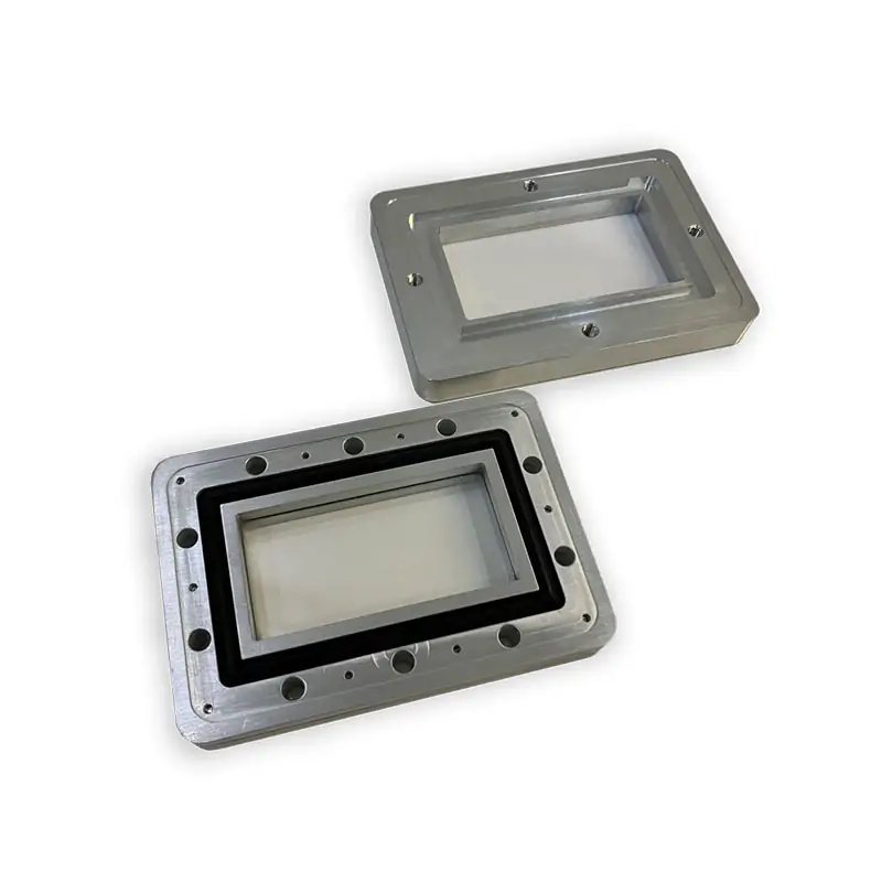
Dolph Microwave supplies standard and custom waveguide pressure windows for 915 MHz and 2450 MHz microwave systems, with published 6 kW, 10 kW and up to 20 kW CW options. Choose 16 mm, 26 mm or custom thickness, glass, quartz or ceramic window material, and aluminum or copper construction. Send frequency, power, waveguide size, pressure and flange data for model selection or a custom build.
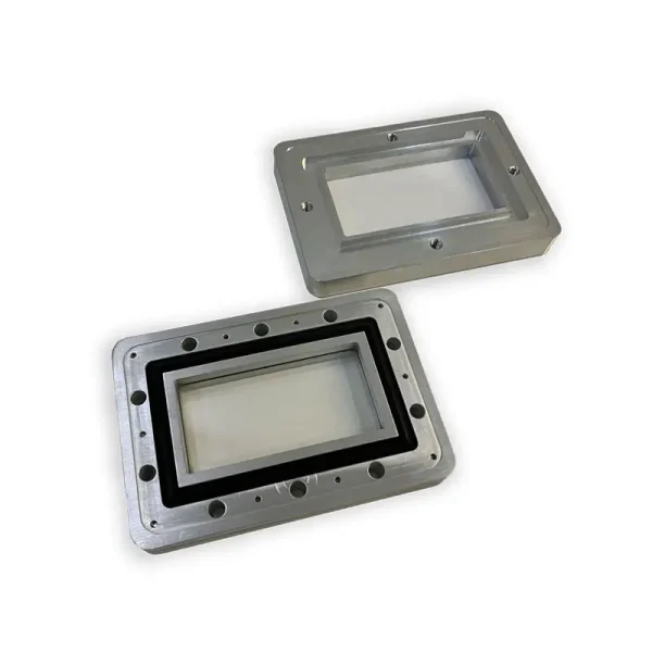
Built Around Your Frequency, Power and Pressure
For sealed high-power waveguide lines, Dolph matches the window material, thickness, body material and flange interface to the operating point you send. Standard and custom builds are available.
High-Power Configuration Data
Use these values for the first selection. Final construction is confirmed against your waveguide and flange interface.
| Frequency Range | 915 MHz and 2450 MHz |
|---|---|
| Handling Power | 6 kW, 10 kW, up to 20 kW CW |
| Thickness | 16 mm, 26 mm, or other thickness on request |
| Window Material | Glass, quartz, ceramics |
| Body Material | Aluminum (Al) / Copper (Cu) |
| Configuration | Standard or customized upon request |
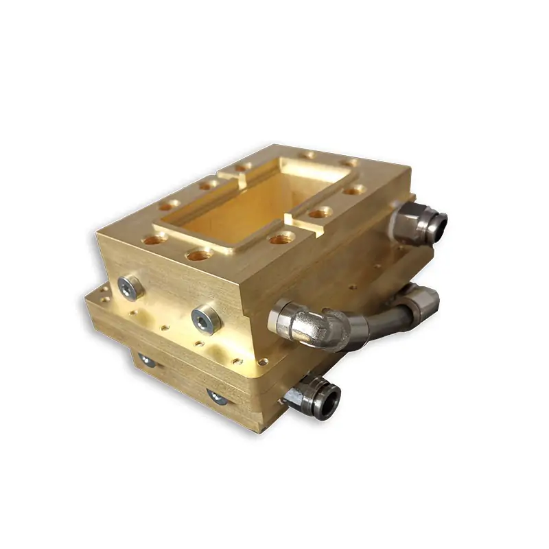
For a broader standard rectangular-waveguide range outside the 915 MHz and 2450 MHz high-power line, see Waveguide Pressure Windows.
Need a direct replacement or non-standard flange?
Send the existing part number, drawing or mating flange dimensions with your operating data.
WPW Datasheet Models
The product PDF lists the following WR430, WR340 and WR284 WPW data. These values are shown separately from the higher-power 915/2450 MHz configurations above.
| Model | WR Type | Frequency (GHz) | VSWR Max. | IL (dB) | Pressure (PSIG) | Handling Power (W) |
|---|---|---|---|---|---|---|
| DH-22WPW… | WR430 | 1.72-2.61 | 1.25 | 0.2 | 15-45 | 100-6000 |
| DH-26WPW… | WR340 | 2.17-3.30 | 1.25 | 0.2 | 15-45 | 100-6000 |
| DH-32WPW… | WR284 | 2.60-3.95 | 1.25 | 0.2 | 15-45 | 100-6000 |
Ordering Code Reference
Use the product code when you already know the waveguide size, thickness and flange arrangement. The datasheet example is:
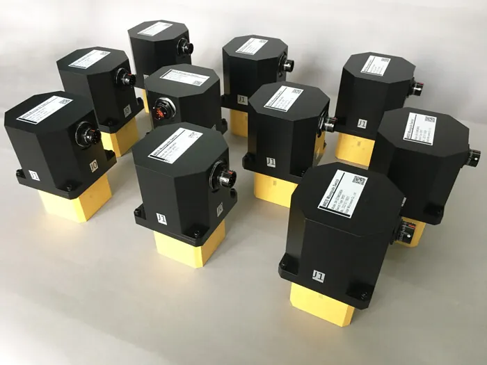
WR340 Build Example
A documented Dolph build shows a practical 2450 MHz configuration. Use it as a reference when your operating point is close to these values.
What to Send for a Technical Quote
A clear operating point lets the engineering team check the right window, flange and material combination before quoting.
RF Data
Frequency, CW or peak power, and acceptable VSWR or insertion-loss limit.
Waveguide Interface
WR/BJ size, flange on both ends, mating-part dimensions or an existing drawing.
Pressure & Temperature
Operating pressure, maximum pressure and operating temperature range.
Build Requirement
Window material, body material, finish, quantity and inspection or document requirements.

Related Waveguide Parts
If you need standard rectangular coverage outside the high-power 915/2450 MHz line, use the broader Waveguide Pressure Windows range.
For a pressurized line that also needs a gas connection or pressure-control point, add a Waveguide Pressure Inlet.
For sealing at adjacent flange joints, match the interface with the correct Waveguide Gasket and O-Ring.
If the pressure window is one part of a larger 915 MHz or 2450 MHz line, review Dolph’s Custom Industrial Microwave Components for matched high-power components.


Technical Downloads
Use the product sheet for WPW model data and the flange document to confirm Dolph flange designations.
Ready for Selection
Send frequency, CW or peak power, WR/BJ size, operating pressure, flange on both ends, preferred window material, temperature range and quantity. Add a drawing when the part must fit an existing assembly.







