Dolph Microwave
Precision Waveguide Calibration Kits
Rectangular waveguide calibration kits provide reference standards for VNA measurements at a waveguide interface. Select the WR size and flange, then match the adapters, calibration method and definition data to your instrument. The listed frequency span covers multiple models; one kit does not cover the entire range.

- Combined model coverage
- 0.76–112 GHz
- Waveguide sizes
- WR975–WR10
- Offset sections
- 1/8λ · 1/4λ · 3/8λ
Before you order
Match the kit to the instrument and fixture
Adapter interfaces
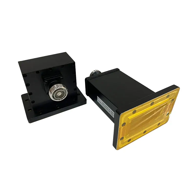
The kit description includes two waveguide-to-coaxial adapters. Connector options include N, SMA, 2.92 mm, 1.85 mm and 1.0 mm, depending on the model.
Components and offset lengths
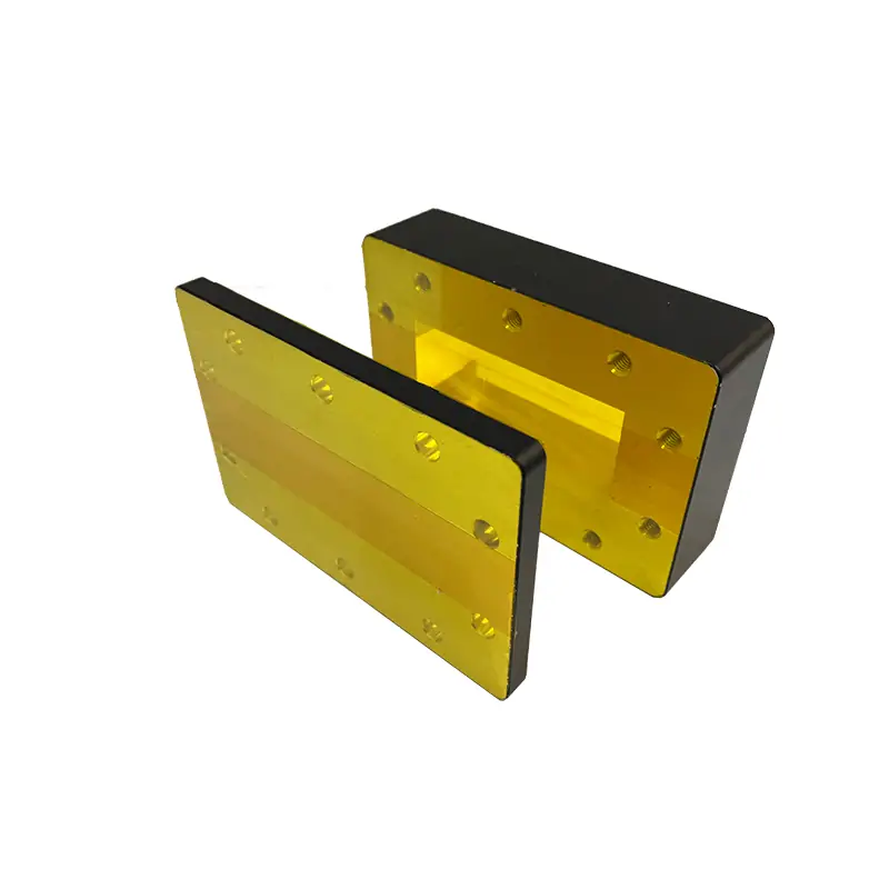
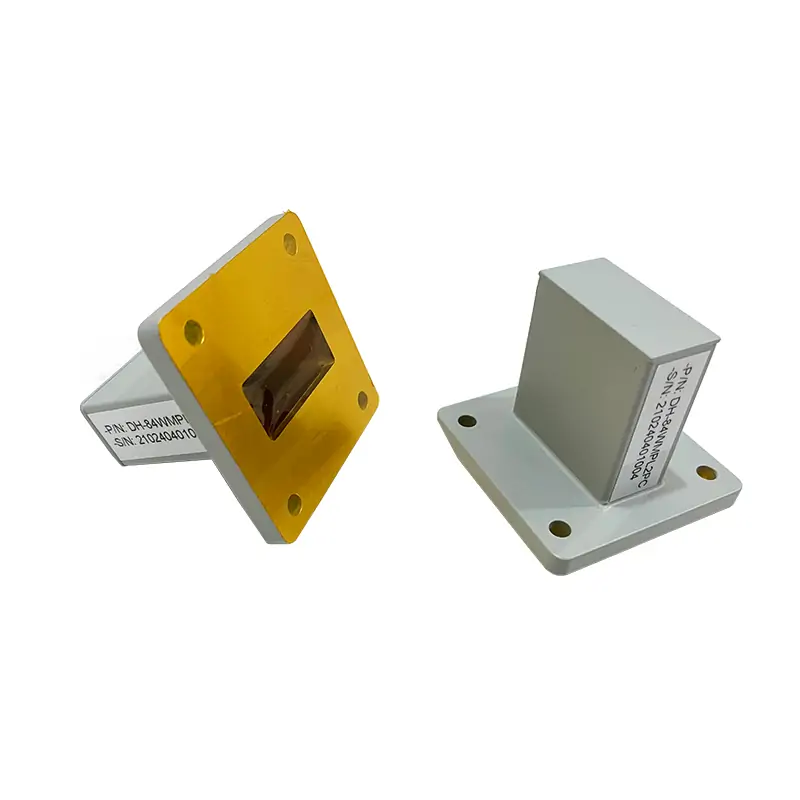
The kit includes a termination, short and waveguide offset sections. The matrix lists the actual offset thicknesses, rather than one set of dimensions for every band.
Calibration files
Specify the VNA model, firmware and calibration method, then request the matching definition file or coefficient sheet. Connector fit alone does not establish software compatibility or measurement accuracy.
If you only need individual components, compare waveguide shorts and shorting plates and waveguide-to-coaxial adapters.

For the rest of your setup
Does your method need a sliding load?
Lower-band kit options may include a sliding load. Specify the intended calibration method and confirm the component list for the exact kit you need.
View waveguide sliding terminationsTechnical data
Specifications & dimensions
Swipe or scroll across the table to see all columns.
| MODEL | FREQUENCY RANGE (GHz) | WG SIZE | ADAPTERS (VSWR) | TERMINATION (VSWR) | SHORT (VSWR) | WAVEGUIDE OFFSETS THK.(mm) | HARDWARE (SCREWS/NUTS/WASHERS) | STORAGE CASE | FLANGES TYPE | DATASHEET | ||||
|---|---|---|---|---|---|---|---|---|---|---|---|---|---|---|
| FEMALE CONNECTOR | MALE CONNECTOR | 1/8λ Section | 1/4λ Section | 3/8λ Section | COVER | |||||||||
| DH-9VNAWKN | 0.76-1.15 | WR975 | 1.2:1 | 1.2:1 | 1.03 | 60 | 50.79 | 101.58 | 152.37 | 1 set | 1 | UDR9 | STEP | |
| DH-12VNAWKN | 0.96-1.46 | WR770 | 1.2:1 | 1.2:1 | 1.03 | 60 | 40.07 | 80.14 | 120.21 | 1 set | 1 | UDR12 | STEP | |
| DH-14VNAWKN | 1.13-1.73 | WR650 | 1.2:1 | 1.2:1 | 1.03 | 60 | 33.96 | 67.92 | 101.88 | 1 set | 1 | UDR14 | STEP | |
| DH-18VNAWKN | 1.45-2.2 | WR510 | 1.2:1 | 1.2:1 | 1.03 | 60 | 26.58 | 53.17 | 79.75 | 1 set | 1 | UDR18 | STEP | |
| DH-22VNAWKN | 1.72-2.61 | WR430 | 1.2:1 | 1.2:1 | 1.03 | 60 | 22.41 | 44.81 | 67.22 | 1 set | 1 | UDR22 | STEP | |
| DH-26VNAWKN | 2.17-3.3 | WR340 | 1.2:1 | 1.2:1 | 1.03 | 60 | 17.75 | 35.50 | 53.25 | 1 set | 1 | UDR26 | STEP | |
| DH-32VNAWKN | 2.6-3.95 | WR284 | 1.2:1 | 1.2:1 | 1.03 | 60 | 14.82 | 29.64 | 44.46 | 1 set | 1 | UDR32 | STEP | |
| DH-40VNAWKN | 3.22-4.9 | WR229 | 1.2:1 | 1.2:1 | 1.03 | 60 | 11.96 | 23.92 | 35.87 | 1 set | 1 | UDR40 | STEP | |
| DH-48VNAWKN | 3.94-5.99 | WR187 | 1.2:1 | 1.2:1 | 1.03 | 60 | 9.78 | 19.56 | 29.34 | 1 set | 1 | UDR48 | STEP | |
| DH-58VNAWKN | 4.64-7.05 | WR159 | 1.2:1 | 1.2:1 | 1.03 | 60 | 8.31 | 16.62 | 24.93 | 1 set | 1 | UDR58 | STEP | |
| DH-70VNAWKN | 5.38-8.17 | WR137 | 1.2:1 | 1.2:1 | 1.03 | 60 | 7.17 | 14.33 | 21.50 | 1 set | 1 | UDR70 | STEP | |
| DH-84-VNAWKN | 6.57-9.99 | WR112 | 1.2:1 | 1.2:1 | 1.03 | 60 | 5.87 | 11.73 | 17.60 | 1 set | 1 | UDR84/UBR84 | STEP | |
| DH-100VNAWKN | 8.2-12.5 | WR90 | 1.2:1 | 1.2:1 | 1.03 | 60 | 4.69 | 9.37 | 14.06 | 1 set | 1 | UDR100/UBR100 | STEP | |
| DH-120VNAWKN | 9.84-15 | WR75 | 1.2:1 | 1.2:1 | 1.03 | 60 | 3.90 | 7.81 | 11.71 | 1 set | 1 | UBR120 | STEP | |
| DH-140VNAWKS | 11.9-18 | WR62 | 1.2:1 | 1.2:1 | 1.03 | 60 | 3.25 | 6.49 | 9.74 | 1 set | 1 | UBR140 | STEP | |
| DH-180VNAWKS | 14.5-22 | WR51 | 1.2:1 | 1.2:1 | 1.03 | 60 | 2.66 | 5.32 | 7.98 | 1 set | 1 | UBR180 | STEP | |
| DH-220VNAWKK | 17.6-26.7 | WR42 | 1.2:1 | 1.2:1 | 1.03 | 60 | 2.19 | 4.38 | 6.57 | 1 set | 1 | UBR220 | STEP | |
| DH-260VNAWKK | 21.7-33 | WR34 | 1.2:1 | 1.2:1 | 1.03 | 60 | 1.78 | 3.55 | 5.33 | 1 set | 1 | UBR260 | STEP | |
| DH-320VNAWKK | 26.3-40 | WR28 | 1.2:1 | 1.2:1 | 1.03 | 60 | 1.47 | 2.93 | 4.40 | 1 set | 1 | UBR320 | STEP | |
| DH-400VNAWKV | 32.9-50.1 | WR22 | 1.2:1 | 1.2:1 | 1.03 | 60 | 1.17 | 2.34 | 3.51 | 1 set | 1 | FUGP400/UG-383U/M | STEP | |
| DH-500VNAWK1.85 | 39.2-59.6 | WR19 | 1.3:1 | 1.3:1 | 1.03 | 60 | 0.98 | 1.97 | 2.95 | 1 set | 1 | FUGP500/UG-383U/M | STEP | |
| DH-620VNAWK1.85 | 49.8-75.8 | WR15 | 1.3:1 | 1.3:1 | 1.03 | 60 | 0.77 | 1.54 | 2.31 | 1 set | 1 | FUGP620/UG-385U/M | STEP | |
| DH-740WNAWK1.0 | 60.5-91.9 | WR12 | 1.4:1 | 1.4:1 | 1.03 | 60 | 0.64 | 1.27 | 1.91 | 1 set | 1 | FUGP740/UG-387U/M | STEP | |
| DH-900WNAWK1.0 | 73.8-112 | WR10 | 1.4:1 | 1.4:1 | 1.03 | 60 | 0.52 | 1.05 | 1.57 | 1 set | 1 | FUGP900/UG-387U/M | STEP | |
| Part Number Guide: DH-100VNAWKN “100”—Waveguide Size | WR90 “VNAWK”—Waveguide Type | Precision Waveguide Calibration Kits “N”— Adapters Conector-Style | N-Type “S”— Adapters Conector-Style | SMA-Type “K”— Adapters Conector-Style | 2.92mm “1.85”— Adapters Conector-Style | 1.85mm “1.0”— Adapters Conector-Style | 1.0mm “A/C”— Material | Aluminium, Cu | ||||||||||||||
| Note: All Dolph-MW models include an surtec/corrosion protection treatment and are painted flat black. Flanges are unplated, polished and surtec. Other finishes and paint colors are available upon request. | ||||||||||||||
Materials & ordering options
Define the calibration setup before selecting a kit
The kit component checklist distinguishes reflective shorts from matched loads and identifies the offset sections and adapters. A short should reflect strongly; a termination should absorb the incident wave. Their VSWR entries are not interchangeable acceptance limits.
For TRL, select line standards that give suitable phase separation from the thru across the measurement band. A nominal fractional-wavelength label alone does not prove full-band coverage. Confirm the line lengths, reference planes and definitions used by the VNA.[1]
Use the waveguide calibration workflow to plan flange inspection, instrument settings and an independent verification measurement. Include the DUT interfaces and fixtures when specifying the wider RF test and measurement setup.
Use the model table for initial selection. Before ordering, obtain the current model-specific drawing, component list and calibration data revision; confirm any difference between the web table, general catalog and quoted configuration.
Technical documents
Questions before ordering
Can I use the kit with any VNA?
The connector, measurement band and calibration definitions must match the instrument setup. Send the VNA model and required data format before ordering.
Can I replace only one calibration component?
Identify the existing kit and the missing component, including flange code and offset dimensions. The component can then be checked against the original kit specification.
Related products

Waveguide Shorts/Shorting Plates
View productFor individual waveguide shorting components.
Standard Waveguide_High-Power Waveguide Coaxial Adapter
View productFor the waveguide-to-coaxial test interface.

Waveguide Calibration and Verification Kits
View productTo compare calibration and verification options.
Tell us what you need
Have a model or drawing?
Send the VNA model and firmware, sweep band, WR size, flange drawing, coaxial interfaces and calibration method. State the required data format, verification artifact and documentation so the quoted kit can be checked against your test setup.