Manual 3-Stub Matching for High-Power Microwave Lines
Use a manual three-stub tuner when an industrial microwave load needs impedance adjustment at 915 MHz or 2450 MHz. Select the WR interface, power and cooling version, and provide access to the adjustment points in the installation drawing.
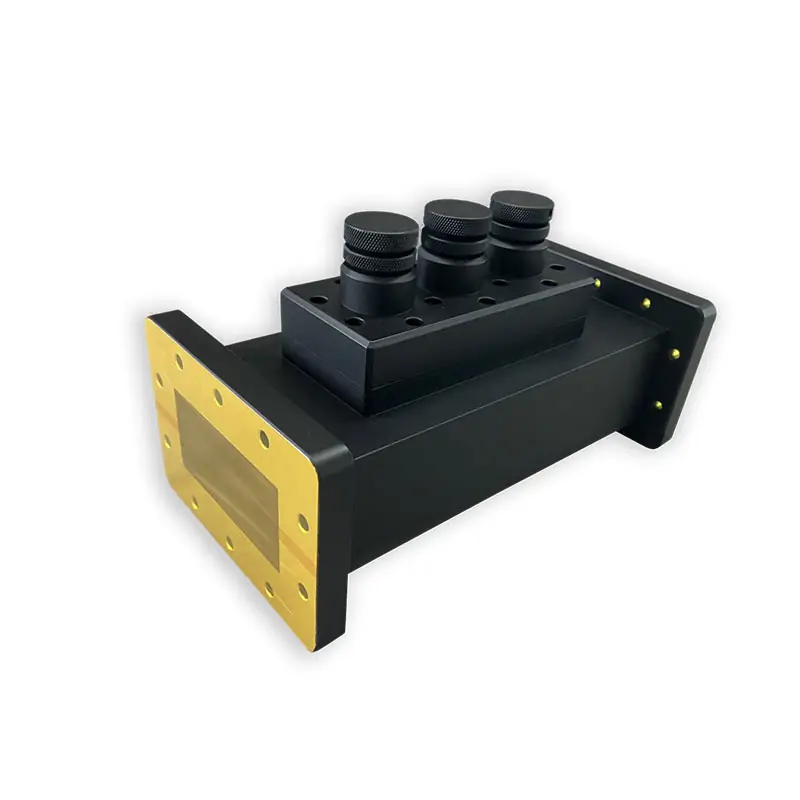
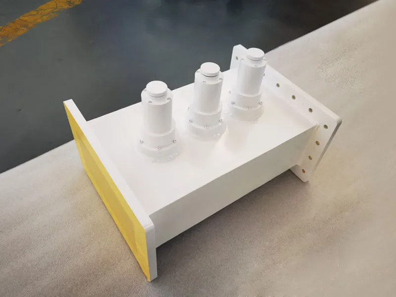
Built to Match the Load in a High-Power Waveguide Line
Adjusting the three stubs changes the impedance seen at the source-side reference plane. This can reduce reflected power at that plane for a suitable load; it does not remove every standing wave on the load side or guarantee a fixed final VSWR for all loads.
For replacement work, send the existing waveguide size, flange type, operating frequency, CW power and an installation drawing or clear interface photo. If your requirement is an adjustable short-circuit section instead, use a microwave sliding short.
See the 915 / 2450 MHz Component LineCatalog Product Specifications
These product details are kept in the same wording used in the original tuner specification.
The feature summary includes WR430, but the detailed table lists WR975, WR340 and WR284 configurations. Confirm any unlisted interface and the operating-band suitability of the selected WR size instead of extrapolating from the family description.
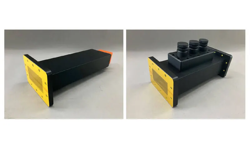
Standard Model Matrix
The model rows distinguish a 15 kW air-cooled 915 MHz version, 6 kW air-cooled 2450 MHz versions and a 10 kW water-cooled WR340 version. The original “VSWR Max. 1.1–10.0” entries are retained; request their tuning-range definition and the achievable match for the specified load.
| Model | WR Type | Frequency (MHZ) | VSWR Max. | Handling Power (KW) | Cooling | Tuning | Flange Type | Inside Finish | Body Finish | Material |
|---|---|---|---|---|---|---|---|---|---|---|
| DH-9W3ST915PPA… | WR975 | 915±30 | 1.1-10.0 | 15 | Air | Manual | Cover/Grooved | Iridite per MIL-C-5541 | Anticorrosion Black Painted | Al |
| DH-26W3ST2450PPA… | WR340 | 2450±25 | 1.1-10.0 | 6 | Air | Manual | Cover/Grooved | Iridite per MIL-C-5541 | Anticorrosion Black Painted | Al |
| DH-26WW3ST2450PPA… | WR340 | 2450±25 | 1.1-10.0 | 10 | Water | Manual | Cover/Grooved | Iridite per MIL-C-5541 | Anticorrosion Black Painted | Al |
| DH-32W3ST2450PPA… | WR284 | 2450±25 | 1.1-10.0 | 6 | Air | Manual | Cover/Grooved | Iridite per MIL-C-5541 | Anticorrosion Black Painted | Al |
Already have a model number or an old tuner drawing? Send it with the operating power and mating flange information for a faster cross-check.
Confirm a Tuner ModelOrdering Information
Catalog code example: DH – 26 W3ST 2450 P M A
Send These Details for a Quote
Provide the load impedance or measured reflection data at a defined reference plane if available. Add the required match over frequency, operating power and installation details below so the proposed tuner can be assessed against the actual load.
Operating Frequency
Center frequency and tolerance. Catalog rows cover 915±30 MHz and 2450±25 MHz.
CW Power
State the continuous operating power and duty condition used by the line.
Waveguide Size
Send the WR type, or the mating waveguide dimensions when replacing a non-standard part.
Flange Interface
Confirm cover or grooved flange and include the mating designation if known.
Cooling
Catalog configurations include air cooling and water cooling. Use the quoted cooling version for the selected power configuration.
Installation Drawing
Include available length, adjacent components and interface dimensions when the tuner must fit an existing line.
Manufacturing and Inspection Support
Dolph Microwave states that it has manufactured microwave components since 2001. Its published capabilities include CNC machining, turning, waveguide forming and bending, soldering and brazing, plating, anodising and passivation, laboratory work and microwave-chamber testing.
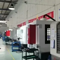
CNC Workshop

Testing Laboratory
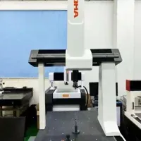
Dimensional Inspection

Microwave Chamber



Complete the Microwave Line with the Right Components
Use the tuner for impedance matching. Add other components only when the system function requires them.
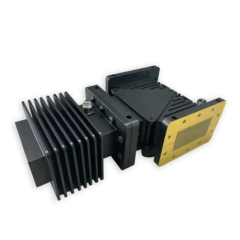
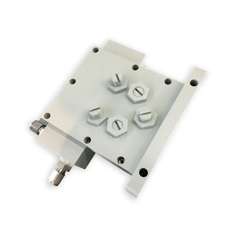
For reflected-power protection around the source, review the microwave isolator or microwave circulator.
For power sampling or measurement, use a microwave coupler. For absorbing microwave power during system operation or testing, review the microwave water load.
If several high-power parts must be matched to the same line, see our custom industrial microwave components capability.
Need a Standard Model or a Custom Fit?
Send the operating frequency, CW power, waveguide size, flange type and installation drawing. We can check the catalog configuration first and quote a customized mechanical version when the interface requires it.
Technical Files
Use the original tuner datasheet for model reference and the flange document when checking the mating interface.