
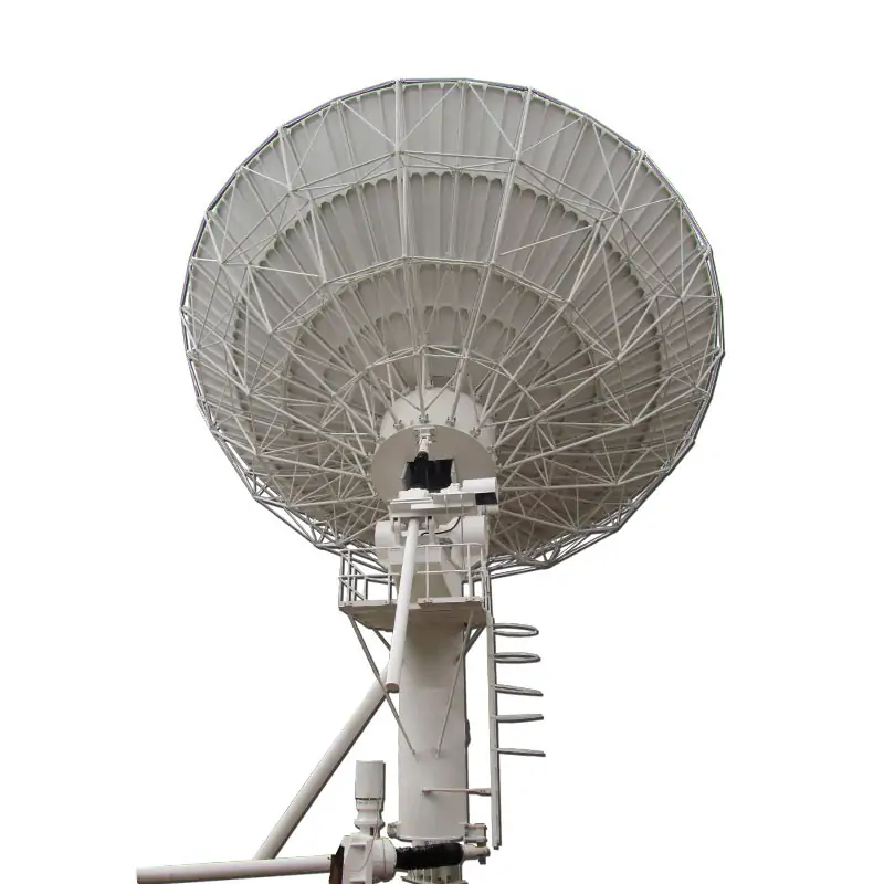
11.3 Meter Dual-Reflector Earth Station Antenna | DH 11.3M DR
A fixed large-aperture earth station antenna for satellite data, voice and broadcast links. The published Ku-band configuration provides 61.4 dBi receive gain, 62.32 dBi transmit gain, 1.3:1 VSWR and 125 mph (200 km/h) survival wind performance, with manual or motorized jack-screw drive and field-changeable feed configurations.

Published 11.3 Meter Configuration
Type: DH 11.3 Meter DR Ku-band Antenna. The reflector uses stretch-formed doubly contoured panels with matched radials and hub for field alignment. The elevation-over-azimuth LMA pedestal is specified for stiffness, stability, orbital-arc coverage and fine drive performance required for Ku-band pointing.
Configuration Details
The product page lists C-band, Ku-band and Ka-band feed options and LP/CP configurations. The published 11.3 meter data sheet provides detailed Ku-band linear performance and also notes X- (Military/WGS), C-, or Ka-band capabilities. Band, polarization and feed configuration should be confirmed for the required antenna build.
RF & Antenna Specifications
| Ku-band Linear | Receive | Transmit |
|---|---|---|
| Frequency, GHz | 10.95-12.75 | 13.75-14.5 |
| Mid-Band Gain, dBi | 61.4 | 62.32 |
| VSWR | 1.3:1 | 1.3:1 |
| 3dB Beam Width, deg | 0.15 | 0.13 |
| Noise Temperature | ||
| 10 Deg Elevation, K | 73 | |
| 20 Deg Elevation, K | 65 | |
| Typical G/T @ 10 Degrees | 38.7 | |
| Port to Port Isolation Tx to Rx (same band),dB | 85 | |
| Tx Power Capability, KW | 1 | |
| Cross-pol. on Axis, dB | 35 | 35 |
| Insertion Loss, dB | 0.30 | 0.25 |
| Feed Interface | WR-75 CPR | WR-75 CPR |
| Radiation Pattern Compliance | FCC 25.209, ITU-RS.580-6, | |
| First sidelobe, dB | ≤ -14 | |
| Sidelobe Envelope | 32 – 25 log (1°≤θ<20°) |
The data sheet also states that RF specifications can meet FCC 25.209, IESS and ITU-RS.580-5, with INMARSAT, ASIASAT, INTELSAT, APT and Chinasat referenced. Its key-feature list states type approval from Intelsat / Asiasat / APT / Chinasat.
Confirm the RF and Site Configuration Before Quotation
Send the required band, Tx/Rx frequencies, polarization, site wind condition, foundation preference, drive type and RF interface.
Mechanical Specifications
Non-penetrating mount (NPM)
Azimuth axis configuration
Reflector SurfaceAluminum panels with high-diffusing
white paint
Backup StructureGalvanized steel parts/ Hot Dipped
Galvanized After Fabrication Galvanized
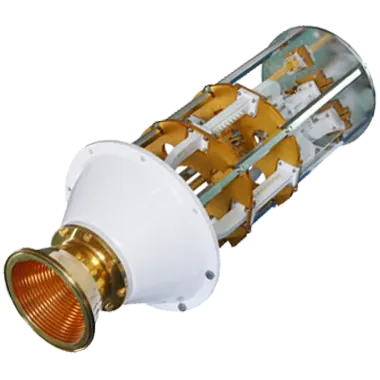
Feed and RF Chain Integration
If your 11.3 meter antenna scope includes the RF feed chain, Dolph can configure feed systems around the required band, polarization, dish type and interface. Dolph’s feed-system portfolio includes feed horns, OMTs, filters, diplexers, polarizers, rotary joints and complete RF networks.
For complete antenna projects, Dolph states that its own feed and waveguide parts can be integrated with antennas supplied through partner factories. This keeps the antenna, feed and waveguide scope aligned without presenting partner-built antenna hardware as in-house microwave-component production.
Review Custom Antenna Feed Systems or the Antenna Feeder Networks when the antenna quotation also requires a feed or waveguide sub-system.
Available Features and Options
How Dolph Supports the RF Scope
Dolph was founded in 2001. For Dolph-built microwave and feed components, the company lists CNC machining, turning, waveguide forming and bending, brazing, assembly and other controlled manufacturing processes.
Feed-system work is supported by Dolph’s testing laboratory and on-site hybrid anechoic chamber. These facilities apply to Dolph-built feed and microwave components; final antenna-project scope should be confirmed in the quotation.
See Manufacturing and About Dolph for the company’s published manufacturing and quality background.


Applications
Enhances international communication networks with high-capacity satellite links.
Serves as a backbone for television and radio broadcasting, supporting both live and scheduled content distribution.
Facilitates robust data and voice transmission for commercial and governmental entities.
Acts as a central hub for satellite data transit and reception, supporting extensive network infrastructures.
Enables high-bandwidth data collection and transmission for space exploration and environmental monitoring.
Send the Details Needed for an Accurate Quote
Operating band and Tx/Rx frequencies, polarization, RF interface, site wind requirement, foundation preference and manual or motorized drive requirement.
Related Earth Station Antenna Options
If the 11.3 meter aperture is not the right fit for your link budget, foundation or site layout, compare smaller Dolph earth station platforms before final selection.
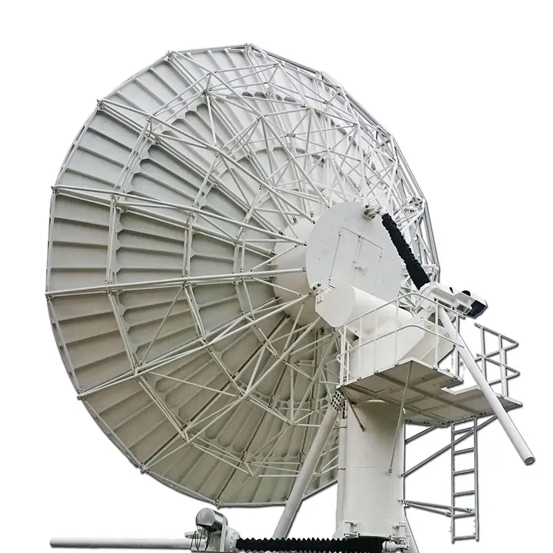
9.0 Meter Earth Station Antenna
A smaller dual-reflector earth station platform with C, Ku and Ka feed options published on the product page.

6.2/7.3 Meter Large Size Antenna
Dual-reflector large-aperture alternatives with manual or motorized operation and multiple feed configurations.

3.7/4.5 Meter Dual-Reflector Earth Station Antenna
A more compact dual-reflector option for projects that do not require an 11.3 meter aperture.
Technical References
For projects using a customized feed chain, see multi-band antenna feed network integration and waveguide feed-to-dish connection guidance.
Dolph publishes a one-year warranty covering defective material and workmanship from the date of delivery, subject to the published warranty terms.
11.3 Meter Data Sheet
The published PDF contains the Ku-band RF table, mechanical specifications, environmental limits, feed interface and radiation-pattern references shown above.
11.3 Meter Dual-Reflector Earth Station Antennas System Data Sheet






