+86 29 8881 0979

default

What are the 4 Main Components in Antenna Equipment

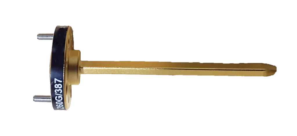
Antenna equipment primarily includes radiating elements (e.g., 20mm×20mm microstrip patches for 2.4GHz operation), feeding networks (RG-58 coaxial cables with 50Ω impedance, <0.5dB/10m loss at 1GHz), matching circuits (π-type networks using 10nH inductors and 10pF capacitors for impedance tuning), and enclosure/support structures (aluminum alloy with 237W/m·K thermal conductivity, IP67-rated for dust/water resistance). Metal Radiator Structure​​ A […]

What are the 4 Main Components in Antenna Equipment Read More »

5 Benefits of Using Waveguide Transfer Switches

Waveguide transfer switches deliver high RF power handling (50W+ vs. 10W coaxial), low insertion loss (<0.5dB at 10GHz), and fast switching (<10ms), with >80dB EMI shielding and MTBF >100,000 hours, ensuring reliability in radar/communication systems. Low Signal Loss Performance Waveguide transfer switches excel here, typically exhibiting an insertion loss of only ​​0.1 dB to 0.25

5 Benefits of Using Waveguide Transfer Switches Read More »

What are the 6 most common waveguide antenna failures

Common waveguide antenna failures include: oxidation (VSWR >1.8 with 0.005mm oxide layer), mechanical deformation (>0.1mm causing 0.5dB loss), moisture ingress (30% failure rise at >85% humidity), solder cracks (post -40°C/+85°C 100 cycles), frequency drift (±5ppm/°C shift), and surface scratches (>0.01mm deep reducing return loss <15dB). Physical Damage and Dents In fact, a single dent with

What are the 6 most common waveguide antenna failures Read More »

How to integrate waveguide components into existing RF systems

To integrate waveguide components into existing RF systems, first align frequencies: verify the system’s operating band (e.g., X-band 8–12GHz) overlaps with the component’s specified bandwidth (e.g., WR-90 covers 8.2–12.4GHz, ≥90% overlap). Use precision-machined flanges (e.g., standard WR-90, ±0.05mm tolerance) and torque to 15N·m with a calibrated wrench to minimize VSWR. Validate via vector network analyzer,

How to integrate waveguide components into existing RF systems Read More »

How does electromagnetic waveguide theory apply to antenna design

Electromagnetic waveguide theory underpins antenna design by shaping radiation patterns and optimizing feed structures. For example, rectangular waveguides—common in horn antennas—operate at 10 GHz using a 22.86mm height (WR-90 standard), supporting TE10 mode with a cutoff frequency of ~6.56 GHz. Impedance matching via waveguide-to-microstrip transitions reduces VSWR to <1.5, enhancing power transfer efficiency by 20-30%

How does electromagnetic waveguide theory apply to antenna design Read More »

What are the 5 key factors in waveguide component durability

Waveguide component durability hinges on material (316L stainless steel with ≥1000hr ASTM B117 salt spray resistance), surface treatment (2-5μm nickel plating), TIG welding (HAZ ≤0.1mm), operating temp (-65°C to +200°C), and vibration resistance (IEC 61373 Cat1 compliance). Material Selection and Properties For instance, while aluminum (6061-T6) is a popular, cost-effective choice for many commercial applications,

What are the 5 key factors in waveguide component durability Read More »

How to calibrate waveguide feed systems for optimal performance

Calibrate waveguide feeds using a network analyzer: measure VSWR (target ≤1.2) and insertion loss (<0.5dB) across 8–12GHz, adjust phase/amplitude with SOLT standards for impedance matching. Check Connections and Cables These faults rarely cause complete failure but instead introduce intermittent signal loss, phase noise, and return loss degradation, often manifesting as a ​​3 dB to 6

How to calibrate waveguide feed systems for optimal performance Read More »

How to measure waveguide antenna radiation patterns

To measure waveguide antenna radiation patterns, use a vector network analyzer in an anechoic chamber: mount the antenna on a precision turntable, scan azimuth/elevation angles at 5° steps (2–40 GHz), capture S-parameters, and apply Fourier transforms to generate 3D pattern data, verifying gain and sidelobe levels. Set Up Test Equipment For a standard X-band waveguide

How to measure waveguide antenna radiation patterns Read More »

How to upgrade traditional antennas with waveguide technology

Upgrade traditional antennas by integrating a waveguide feed to replace the conventional dipole. This modification can boost gain by 3-6 dB and efficiently handle higher frequencies (2-40 GHz) with minimal loss. Precisely couple the waveguide port to the antenna’s feed point and ensure a weatherproof seal to prevent moisture degradation. Waveguide Basics Explained For a

How to upgrade traditional antennas with waveguide technology Read More »

What are the 5 steps to install a waveguide antenna system

To install a waveguide antenna system, first align its frequency (e.g., 12–18GHz for Ku-band) with the feed source to minimize insertion loss (<0.5dB). Secure the antenna to a stable mount using 5–8Nm torque, adjust elevation/azimuth via laser alignment, then calibrate VSWR (<1.5) with a network analyzer, and test signal strength (≥-80dBm) to confirm connectivity. Plan

What are the 5 steps to install a waveguide antenna system Read More »

Scroll to Top
Blank Form (#3)