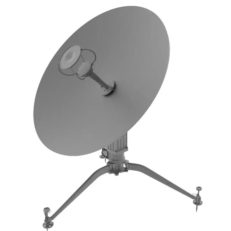

Motorized Quick-Deploy Flyaway SATCOM Antenna
Portable carbon-fiber antenna platform with manual or motorized pointing for temporary satellite links. The published product family covers 0.75 to 4.5 meter reflectors, L, S, C, X, Ku and Ka bands, and single- or dual-band configurations.
The current technical sheet provides detailed RF, mechanical and environmental values for 1.0, 1.2, 1.5, 1.8 and 2.4 meter configurations. Diameter, port, polarization, tracking and control mode can be selected by configuration.
Published Product Scope
Operating formats
The product record lists manual, motorized and driveaway options. This flyaway configuration supports manual or motorized pointing; dedicated vehicle-mounted driveaway systems are linked below.
High-precision mount
Published features include a high-precision antenna mount, low side lobes and high gain.
Carbon-fiber reflector
The published family uses lightweight carbon-fiber reflectors and lists reflector diameters from 0.75 to 4.5 meters.
Band and configuration choices
The product overview lists L, S, C, X, Ku and Ka coverage, single- and dual-band options, and selectable diameter, port, polarization, tracking and control mode. Standard and customized configurations are available on request.
Match the Configuration to Your Link
Send the values that change the antenna build. Dolph can review the published configurations against your operating requirement before quotation.
Send Operating RequirementsExact Rx and Tx frequencies
State the operating band and the actual receive and transmit frequency ranges.
Aperture and reflector type
Confirm the required diameter and any size or transport constraints.
Polarization and feed interface
Specify polarization, required ports and the waveguide interface used by the RF chain.
Pointing and control mode
State manual or motorized pointing and any tracking or controller requirement.
Power and outdoor-unit requirements
Confirm AC or DC supply needs and the BUC, LNB or other outdoor-unit interface.
Site and environmental limits
Provide expected wind, temperature, humidity and deployment conditions that must be checked.
RF & Antenna Specifications
The values below follow the current one-page technical sheet for the listed 1.0, 1.2, 1.5, 1.8 and 2.4 meter configurations.
| Aperture | 1.0 Meter | 1.2 Meter | 1.5 Meter | 1.8 Meter | 2.4 Meter |
|---|---|---|---|---|---|
| Reflector Type | Offset/Ring focus | Offset/Ring focus | Offset | Offset | Gregory Dual Offset |
1.0 / 1.2 Meter Frequency Options
| Optional Freq. Band | Tx, GHz | Rx, GHz |
|---|---|---|
| X-band | 7.90-8.40 | 7.25-7.75 |
| Ku-band | 13.75-14.5 | 10.7-12.75 |
| Ka-band | 27.5~31.0 | 17.7~21.2 |
1.5 / 1.8 / 2.4 Meter Frequency Options
| Optional Freq. Band | Tx, GHz | Rx, GHz |
|---|---|---|
| C-band | 5.85-6.725 | 3.40-4.20 |
| Ku-band | 13.75-14.5 | 10.7-12.75 |
| Ka-band | 27.5~31.0 | 17.7~21.2 |
| RF Parameter | Published Value |
|---|---|
| VSWR | ≤1.25 |
| Axis Ratio, dB | ≤1.5 |
| Cross Pol Iso, dB | ≥35 dB (Axis); ≥32dB (-1dB) |
| Tx/Rx Iso, dB | ≥85 |
| First Side Lobe | ≤-14 dB |
| Side Lobe | 29-25logθ (1° ≤θ <20°); 32-25logθ (20° ≤θ <48°); -10 dB (θ ≥48°) |
| Feed Ports | 2 |
| Feed Interface, 1.0 / 1.2 Meter Group | WR112, WR75, WR28/42 |
| Feed Interface, 1.5 / 1.8 / 2.4 Meter Group | WR137/229, WR75, WR28/42 |
Mechanical & Environmental Specifications
| Material | Carbon Fiber |
|---|---|
| Pointing Type | Manual/Motorized |
| Antenna Coverage | Azimuth: ±180°; Elevation: 10°-90°; Polarization: ±95° |
| Axes Velocities | Azimuth: 0.01°/S-3°/S; Elevation: 0.01°/S-3°/S; Polarization: 1°/S |
| Power Supply | DC 24 V 10A, AC110-230V 50/60Hz 5A (Optional) |
| Operational Wind | 65km/h (40mph) with ballast |
| Temperature | -40° C to +50° C |
| Protection Grade | IP65 (Dust and Water Resistant) |
| Humidity | 0-98% |
Ordering Information
The technical sheet shows the model example DH 1.2 Meter QD Ku-band Antenna and the designation meanings below.
| DH | Dolph Microwave |
|---|---|
| 1.2 | Aperture |
| QD | Quick Deployable |
| QDA | Quick Deploy Auto-Acquire |
| VM | Vehicle-Mount / Drive Away SNG |
| C | C-band |
| Ku | Ku-band |
| Ka | Ka-band |
| C/Ku | Dual-band |
Original Technical Sheet
Use the source sheet together with the final quotation and approved configuration when confirming aperture, band, feed interface, pointing method and environmental requirements.
Download Technical Data SheetUse the Right Deployment Format
If this motorized flyaway format does not match your deployment method, compare the dedicated products below instead of forcing the wrong configuration.
Need one-button satellite acquisition?
Use the 0.9/1.2 Meter Quick Deploy Auto Acquisition Antenna. Its published data lists motorized positioning, one-button auto-pointing and DVB-S1/DVB-S2 acquisition by beacon or modem outputs.
Check Auto-Acquire ModelsNeed a smaller tool-free flyaway kit?
The 1.2M Quick-deploy Flyaway Antenna publishes a six-piece carbon-fiber reflector, pre-assembled tripod base, Ku/Ka feed options, adjustable feet and approximately five-minute tool-free setup.
For larger portable apertures, compare the 1.8/2.4M Quick Deploy Antenna, which has separate model data sheets for RF, mechanical, transport and environmental values.
Compare SATCOM Antennas

Need a vehicle-mounted driveaway system?
Use the 1.2/1.5/1.8/2.4 Meter Vehicle Mounted Driveaway SNG Antenna when the antenna must be integrated on a vehicle platform. Its published scope includes three motorized axes, an integrated auto-locate controller and manual override.
View Driveaway Options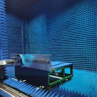
Feed Interface and RF Integration
The flyaway technical sheet lists WR112, WR75, WR28/42 and WR137/229 feed interfaces by configuration group. Send the exact operating band, polarization and mating interface so the feed path can be checked with the antenna build.
For a custom feed chain, see Custom Antenna Feed Systems. For installation planning, the engineering article How to Connect a Waveguide Feed to a Dish Antenna covers feed position, polarization alignment and RF verification.
Manufacturing, Test and Order Support
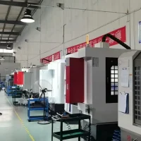
Dolph Microwave was founded in 2001. The company lists CNC machining, turning, waveguide forming and bending, brazing, plating, RF measurement and antenna test facilities among its manufacturing and laboratory capabilities.
Machining and fabrication
Published capabilities include CNC machining, turning, waveguide forming and bending, soldering and brazing, plating and electroforming.

RF measurement
The published capability page lists RF vector and scalar systems up to 100 GHz and high-power transmitters.
Antenna and environmental testing
Published facilities include antenna anechoic chambers and environmental testing for temperature, altitude, salt fog and humidity.
Quality process and warranty
Dolph states that its Quality Manual and Quality Procedure use ISO 9001:2015. The published warranty covers material and workmanship defects for one year from delivery.
Send the Data That Defines Your Antenna
Include exact Rx/Tx frequencies, reflector diameter, polarization, feed interface, pointing and control mode, power supply, site limits, quantity and required timing.