
WEB Code
E-Plane Bend
The published part-number guide identifies “WEB” as the E-bend configuration. Required A × B lengths are stated in millimetres and should be matched to the available installation envelope.
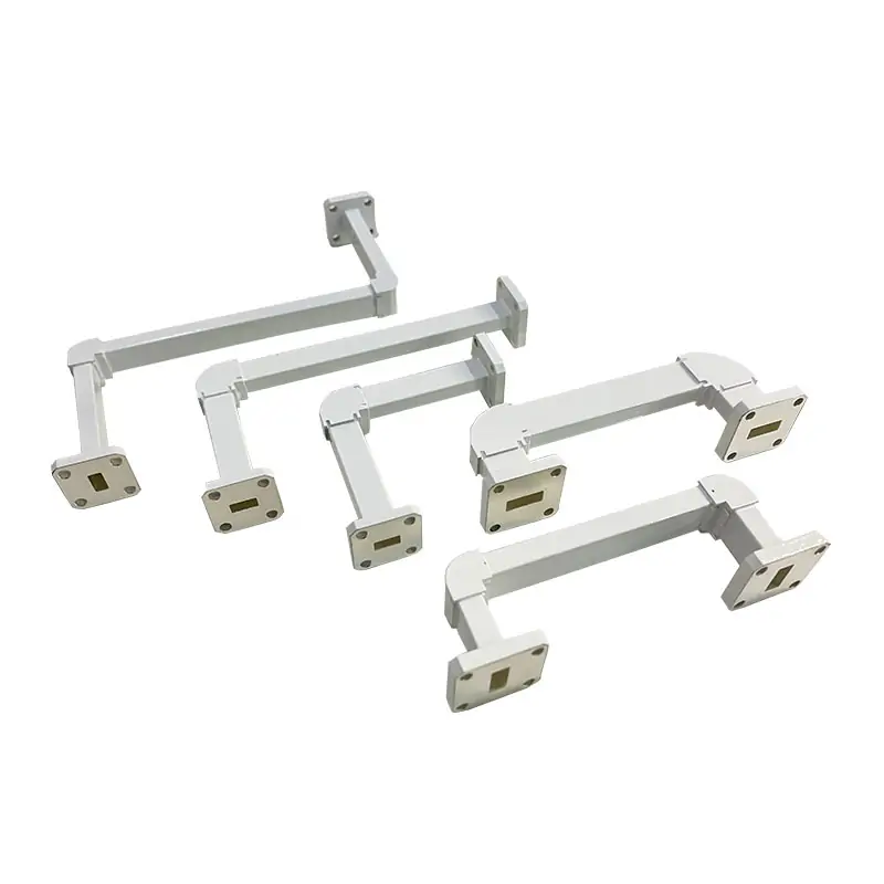
Waveguide bends are essential components in microwave engineering, designed to redirect electromagnetic waves along a desired path within a waveguide system. They facilitate the routing of signals through complex system geometries without significant loss, making them crucial for applications in radar, telecommunications, and satellite communications. Available in various angles and sizes, waveguide bends ensure efficient signal transmission and system integration.
Published Frequency
0.84–40.0 GHz
Waveguide Range
WRD840–WRD180
Published VSWR
1.20:1 or 1.25:1
Catalog IL Listing*
0.15–1.5 dB/m
Standard A × B
50 × 50–200 × 200 mm
Catalog Compliance
RoHS & REACH: Comply
Bend Orientation
The published model code identifies E-bend or H-bend construction.
WEB Code
The published part-number guide identifies “WEB” as the E-bend configuration. Required A × B lengths are stated in millimetres and should be matched to the available installation envelope.
WHB Code
The published part-number guide identifies “WHB” as the H-bend configuration.
Published Catalog Data
The table consolidates the published E-plane and H-plane entries by WRD family.
Swipe horizontally to view all model columns.
| WRD Family / Model PDF | Frequency | VSWR | Catalog IL* | Standard A × B | Cover Flange | Grooved Flange |
|---|---|---|---|---|---|---|
| WRD840 DH-840DRWEB / WHB | 0.84–2.0 GHz | 1.25:1 | 0.2 dB/m | E: 150 × 150 mm H: 200 × 200 mm | FPWRD840U24 | FMWRD840U24 |
| WRD150 DH-150DRWEB / WHB | 1.5–3.6 GHz | 1.25:1 | 0.15 dB/m | E: 100 × 100 mm H: 150 × 150 mm | FPWRD150D24 | FMWRD150D24 |
| WRD200 DH-200DRWEB / WHB | 2.0–4.8 GHz | 1.25:1 | 0.15 dB/m | E: 100 × 100 mm H: 150 × 150 mm | FPWRD200D24 | FMWRD200D24 |
| WRD250 DH-250DRWEB / WHB | 2.6–7.8 GHz | 1.25:1 | 0.15 dB/m | E: 100 × 100 mm H: 150 × 150 mm | FPWRD250D30 | FMWRD250D30 |
| WRD350 DH-350DRWEB / WHB | 3.5–8.2 GHz | 1.25:1 | 0.25 dB/m | E/H: 100 × 100 mm | FPWRD350D24 | FMWRD350D24 |
| WRD475 DH-475DRWEB / WHB | 4.75–11.0 GHz | 1.25:1 | 0.2 dB/m | E/H: 100 × 100 mm | FPWRD475D24 | FMWRD475D24 |
| WRD500 DH-500DRWEB / WHB | 5.0–18.0 GHz | 1.25:1 | 0.5 dB/m | E/H: 80 × 80 mm | FPWRD500D36 | FMWRD500D36 |
| WRD580 DH-580DRWEB / WHB | 5.8–16.0 GHz | 1.25:1 | 0.35 dB/m | E/H: 80 × 80 mm | FPWRD580D28 | FMWRD580D28 |
| WRD650 DH-650DRWEB / WHB | 6.5–18.0 GHz | 1.25:1 | 0.35 dB/m | E/H: 50 × 50 mm | FPWRD650D28 | FMWRD650D28 |
| WRD700 DH-700DRWEB / WHB | 7.0–18.5 GHz | 1.25:1 | 0.4 dB/m | E/H: 50 × 50 mm | FPWRD700D26 | FMWRD700D26 |
| WRD750 DH-750DRWEB / WHB | 7.5–18.0 GHz | 1.25:1 | 0.6 dB/m | E/H: 50 × 50 mm | FPWRD750D24 | FMWRD750D24 |
| WRD110 DH-110DRWEB / WHB | 11.0–26.5 GHz | 1.25:1 | 0.75 dB/m | E/H: 50 × 50 mm | FPWRD110C24 | FMWRD110C24 |
| WRD180 DH-180DRWEB / WHB | 18.0–40.0 GHz | 1.20:1 | 1.5 dB/m | E/H: 50 × 50 mm | FPWRD180C24 | FMWRD180C24 |
*Catalog IL field: the current Dolph product table labels this column “IL (dB/m).” Because the published source does not define whether the value represents attenuation per unit length, bend loss or another catalog test convention, treat it as a catalog reference only. Confirm the applicable loss definition, test method and acceptance limit in the approved quotation or model drawing before final selection.
Material and Finish
Aluminum or copper, listed as Al/Cu in the model table.
The model table lists Chromate/Painted. The published product note also describes iridite/corrosion-protection treatment and flat-black paint.
Other finishes and paint colours are stated as available on request.
Where a specific alloy, temper or copper grade is required, state it in the RFQ.
Flange Interfaces
The published part-number guide identifies “P” as the rectangular flat flange option.
The published part-number guide identifies “M” as the rectangular grooved flange option.
FPWRD cover flanges and FMWRD grooved flanges with model-specific suffixes.
Identify any required IEC, EIA or project-specific interface standard in the purchase specification.
Ordering Code
Published example: DH-840DRWEB150*150PMA.
Required VSWR and loss acceptance limits, including the intended definition and test method.
Required bend angle, bend radius and flange clocking from the installation drawing.
Critical tolerances, datum references and interface dimensions.
Temperature, pressure, leak, power-handling or environmental requirements.
Drawings, dimensional records, material records or electrical test documentation required with delivery.
Prototype and production quantities plus the required delivery timing.
Application Review
Application suitability depends on the complete assembly, operating band, interfaces, installation envelope and project-specific performance limits.
Routing double-ridged waveguide paths around structural and equipment constraints.
Mechanical path changes within feed, uplink and ground-station assemblies.
Waveguide routing where installation space requires E-plane or H-plane direction changes.
Connection of double-ridged waveguide components in laboratory and measurement setups.
Published catalog values support preliminary selection; final dimensions, interfaces, materials, finishes and acceptance limits are defined by the approved quotation and production drawing.
Specification-Based Quotation
Provide the selected WRD family, E-plane or H-plane configuration, A × B dimensions, flange interfaces, material, finish, quantity and any project-specific acceptance requirements.
Technical Downloads
Related components: Double-Ridged Straights & Transitions Double-Ridged Waveguide Tube Double-Ridged Waveguide to Coaxial Adapter







