Specify the Bend Around Your Existing Microwave Line
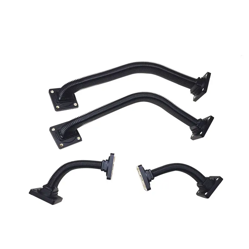
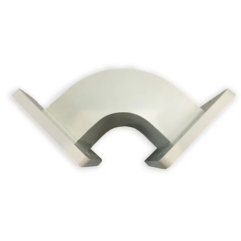
Route the waveguide around equipment using the bend plane and geometry shown on your installation drawing. The product family includes 915 MHz and 2450 MHz applications, but each WR model has its own listed band. Select the model and power configuration together rather than applying the family maximum to every bend.
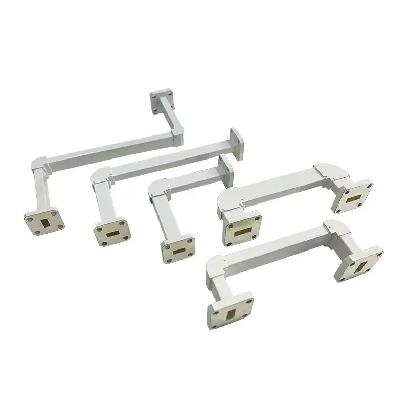
Choose the Geometry That Fits the Installed Run
E-Plane or H-Plane
Give us the bend plane shown on your installed layout or drawing. This prevents the flange orientation and physical route from being guessed from frequency alone.
Sweep or Miter
Both types are listed for this product. Use the available installation envelope, bend plane and mating positions to define the required shape.
45°, 60° or 90°
These angles are listed on the product and datasheet. Include the leg dimensions and surrounding clearance when the bend must fit an existing machine.
Standard or Drawing-Based
Select a catalog model when it matches the system. For a replacement or non-standard layout, send the drawing, STEP file, sketch or old part number for review.
Technical Specifications
The values below combine the listed product specifications and the Microwave Bends datasheet. Final material, flange pair, dimensions and finish should match the approved drawing.
| Specification | Available / Listed Detail | Send With RFQ |
|---|---|---|
| Operating Frequency | 915 MHz and 2450 MHz | Exact operating frequency |
| Handling Power | 6 kW, 10 kW, up to 20 kW CW | Continuous power and any peak-power condition |
| Bend Plane | E-plane or H-plane | Required plane and installed orientation |
| Geometry | Sweep or miter | Required geometry or mechanical drawing |
| Bend Angle | 45°, 60°, 90° | Angle plus leg dimensions / available envelope |
| Material | Product feature list: Aluminum (Al), Copper (Cu) | Required material |
| Mechanical Configuration | Standard and customized configurations | WR size, A × B, flange pair, clocking and drawing |
| Catalog VSWR | 1.1 maximum for the five models in the Microwave Bends PDF | Any project-specific acceptance requirement |
Material requires confirmation: the feature list states Al / Cu, while the Microwave Bends model table lists Al / Brass with Iridite per MIL-C-5541 inside finish and anticorrosion black painted body finish. State the required material and finish in the RFQ so the final build is confirmed on the drawing.
Microwave Bends Catalog Models
Check the required frequency against the model row before comparing dimensions. For example, the WR340 row covers 2.17–3.30 GHz, while the WR284 row starts at 2.60 GHz; the latter row does not establish suitability at 2.45 GHz.
| Model | WR Type | Frequency (GHz) | VSWR Max. | STD. Size (mm) |
|---|---|---|---|---|
| DH-9WEB/WHB… | WR975 | 0.75–1.15 | 1.1 | 200 × 200 |
| DH-14WEB/WHB… | WR650 | 1.13–1.73 | 1.1 | 200 × 200 |
| DH-22WEB/WHB… | WR430 | 1.72–2.61 | 1.1 | 190 × 190 |
| DH-26WEB/WHB… | WR340 | 2.17–3.30 | 1.1 | 100 × 100 |
| DH-32WEB/WHB… | WR284 | 2.60–3.95 | 1.1 | 160 × 160 |
Each row gives a WR model band and published dimensions. Confirm which dimensions describe leg length, flange position and overall clearance on the approved drawing; a nominal bend angle alone cannot establish fit.
Machining, Bending, Brazing and Inspection in One Factory
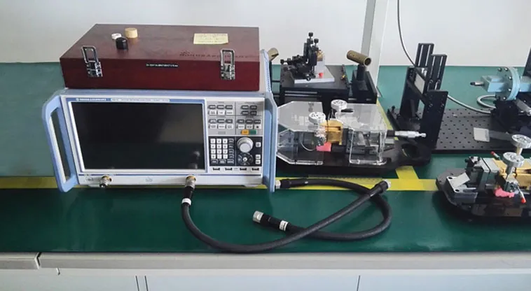
Dolph Microwave lists CNC milling and turning, waveguide forming and bending, soldering and brazing of copper, copper alloys and aluminum, plating, anodising and passivation, CMM inspection and RF measurement among its in-house capabilities.
Machine to the Interface
Flange faces, mounting geometry and external dimensions are made against the selected model or approved drawing.
Form and Join the Bend
Waveguide forming, bending, soldering and brazing are listed factory capabilities for rigid waveguide work.
Check the Dimensions
Dolph Microwave shows coordinate measuring equipment and dimensional inspection capability on its manufacturing pages.
Define the RF Acceptance
If your project needs a specific VSWR, RF sweep, power-handling check or inspection record, put the acceptance requirement in the RFQ.

Ordering Code
DH – 26 WEB A*B P M A
Flange Codes for the Listed WR Sizes
The separate Dolph flange designation file gives the following cover / grooved references for the WR sizes used in the Microwave Bends model table.
Do not order from the WR number alone. Confirm the flange type on both ports against the mating equipment or flange drawing.
Send the Data That Determines the Build
A complete RFQ lets us check fit, interface and power requirements before pricing. Send what is already fixed in your machine; we can review the remaining items with you.
Related Components for the Same Microwave Line
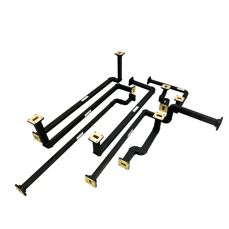
Several Direction Changes in One Assembly
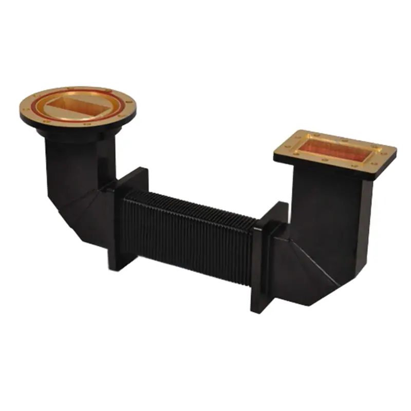
When the route needs more than one bend, a single custom waveguide assembly can combine the bends, straight sections and end interfaces from one system drawing.
Need a Broader Standard Bend Range
For other standard waveguide bands and detailed E-plane / H-plane miter bend models, review our waveguide miter bends.
Need Size or Interface Changes in the Run
If the line also changes waveguide size or interface, pair the bend with a microwave transition or send the complete route for an integrated review.
Engineering References Before You Release the Order
Flange Matching
Check EIA / IEC flange naming, groove style and mating details before finalizing the port configuration.
Waveguide Flange Size GuidePower Definition
Separate CW, peak power and the required acceptance condition when your system has a high-power operating duty.
Waveguide Power HandlingFactory and Quality Information
Download the Technical Files
Keep both files with your RFQ: the Microwave Bends file contains the model table and ordering code; the flange file contains Dolph flange designations and reference data.