
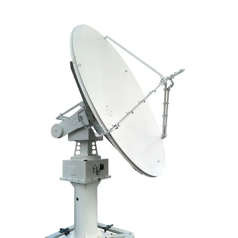
LEO/MEO Satellite Tracking Antenna Systems
2.4 to 7.3 meter X/Y-axis tracking antenna systems for LEO, MEO, HEO and GEO spacecraft. Published configurations include a 2.4 meter X-band antenna and a 3.7 meter S+X dual-band antenna, with program and auto tracking, TLE ephemeris input, Ethernet TCP/IP and M&C software. Platform capability covers L, S, X, C, Ku, Ka, Q and V bands, with low-loss mono-pulse tracking available for higher frequencies and larger apertures.
Built Around the Tracking Requirement
Select the aperture, band combination, feed arrangement and tracking method against your mission data. The published platform uses independent X/Y-axis rotation, program tracking and auto tracking, and supports ephemeris input including Two-Line Element data.
X/Y-Axis Pedestal
Type 1 through Type 4 configurations are published for increasingly larger dishes; the platform also specifies X/Y-axis rotation pedestal non-ballasting technology.
Program + Auto Track
Lights-out operation is published with Ethernet TCP/IP connectivity and M&C software.
TLE Ephemeris Input
Program tracking uses TLE ephemeris data and other supported formats. Transmit/receive feed technologies are published through S+X-band.
Mono-Pulse Option
Low-loss mono-pulse mode coupler tracking is available for high frequencies and larger aperture antennas.
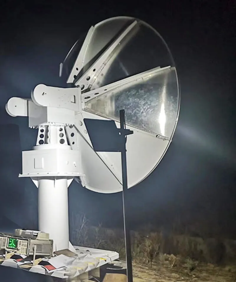
Published Motion and Tracking Performance
Published Mechanical Specifications
| Parameter | DH 2.4 Meter DR X-band Antenna | DH 3.7 Meter DR S+X Dual-band Antenna |
|---|---|---|
| Aperture Size | 2.4 meter | 3.7 meter (5.9 meter Radome) |
| Program Tracking Accuracy | < 0.09°rms | < 0.07°rms |
| Pedestal + Dish Weight | 1500kg | <1700kg |
| Mount | Type1, Type 2, Type3, Type4 Available | |
| Pedestal Configuration | X/Y-axis Rotation Pedestal | |
| Reflector Material | Light aluminum+steel, / Full light aluminum | |
| Range of Motion | X-axis: -90° +90° (zero towards the sky, independent rotation) Y-axis: -90° +90° (zero towards the sky, independent rotation) | |
| Speed Range | X-axis Angular Velocity: 0.01°~10°/s Y-axis Angular Velocity: 0.01°~10°/s | |
| Backlash Travel | < ±1 (arc minute) | |
| Encoder Resolution | ≤0.005° | |
| Servo Position Resolution | ≤0.01° | |
| Pointing Accuracy | S and X frequency bands are better than 1/6 half power beamwidth | |
Published RF Specifications
| Parameter | DH 2.4 Meter DR X-band Antenna | DH 3.7 Meter DR S+X Dual-band Antenna |
|---|---|---|
| Feed Configuration | Prime Focus and Ring-focus, Dichroic Subreflectors | |
| Frequency Range | 9.3~9.7 GHz (Downlink) | 8.025~8.4 Ghz (Downlink) 2.2~2.3 Ghz (Downlink) 2.025~2.1 Ghz (Uplink) |
| Gain(dB) | 45 dBi | X-band 47.63 dBi S-band 35.38 dBi |
| Beamwidth/-3dB | 0.9~1.0° | 0.6° / 2.4° |
| Main-beam matching error | < 0.1° | < 0.1° |
| VSWR | ≤1.5:1 | ≤1.5:1 |
| Polarization | V-/H- Pol. | LHCP/RHCP |
| Axial Ratio | X-band≤0.8dB S-band≤1.2dB | |
| Cross Pol. Isolation | 35 dB | |
| Tx/Rx Isolation | 80dB | 80dB |
| Antenna Noise Temperature | Ta≤77K | X-band Ta≤85K S-band Ta≤130k |
| Feed Interfaces | X-band WR112 | X-band WR112 S-band N-Type |
| First Sidelobes | X-band ≤27 dB S-band ≤27 dB | |
| Sidelobe Leve | 25 dB @ 2.5 degrees main beam 40 dB @ 5.0 degrees main beam | |
Values above reproduce the published Dolph technical datasheet. Final model, feed, radome and performance requirements should be confirmed in the order configuration.
What to Send for Quotation
Orbit and Tracking
Target spacecraft or orbit class, TLE or other ephemeris format, and required tracking mode.
RF Requirement
Transmit and receive bands, frequency range, polarization, feed interface and required RF performance.
Mechanical Requirement
Required aperture, radome need, mount type, installation envelope and site constraints.
Control Interface
Ethernet TCP/IP, M&C integration and any remote-operation or network interface requirements.
If your required configuration is not shown in the published table, send the requirement to Dolph Microwave Sales for review before quotation.
Published Application Scope
Earth Observation
Tracking and reception for Earth observation satellite ground systems.
Remote Sensing
Ground-station tracking and data reception for remote-sensing spacecraft.
Communications
Tracking antenna configurations for satellite communication links.
TT&C
Telemetry, tracking and command functions with program and auto tracking.
Space Exploration
Spacecraft communication support where the selected antenna configuration and link requirements are suitable.
Dolph also publishes the system for LEO, MEO, HEO and GEO spacecraft. For the S+X implementation, see the TT&C, LEO and GEO antenna systems article.
Choose the Closest Antenna Platform
For moving-satellite tracking, use this LEO/MEO platform and send the orbit, tracking and RF requirements for configuration review. For a fixed receive-only station, compare the 2.4/3.0 Meter Rx Only Antenna Systems.
For fixed earth-station requirements that do not need this X/Y moving-satellite tracking architecture, review the Earth Station Antenna range.
For portable field deployment, compare the 0.9/1.2 Meter Quick Deploy Auto Acquisition Antenna and the Motorized Quick Deploy Flyaway Antenna.
For feed-chain work around the reflector, review Antenna Feeder Networks or the Custom Antenna Feed Systems capability page.
Engineering and Supplier Verification
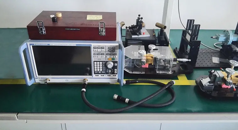
Dolph Microwave states that it was founded in 2001 and manufactures microwave components and antenna feed systems. Its published manufacturing capabilities include CNC machining, turning, waveguide forming and bending, soldering and brazing, plating, electroforming, anodising and passivation, grinding, testing laboratory equipment and a microwave chamber.
The company profile also states that Dolph integrates microwave parts and feed systems with antennas from established suppliers for communication, remote sensing and radar applications. This matters when your project includes both the antenna platform and the RF feed chain.
Dolph publishes an ISO 9001:2015 quality-management certificate covering waveguide component design, manufacture and sale. The posted certificate shows validity through August 7, 2026, so request the current certificate status when compliance documentation is required. The website also publishes a one-year warranty for material and workmanship defects.
Send the Tracking Antenna Requirement
Send the orbit or spacecraft information, frequency plan, required aperture, polarization, tracking method, radome or site limits, control interface and required documentation. Dolph Microwave Sales can review the available configuration and quotation path.
Low/Medium Earth Orbit Satellite Tracking Antenna Systems PDF
Download the original published technical sheet with the mechanical and RF tables for the DH 2.4 Meter DR X-band Antenna and DH 3.7 Meter DR S+X Dual-band Antenna.







