
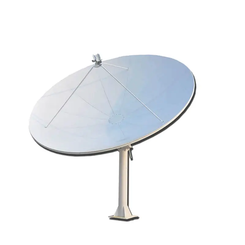
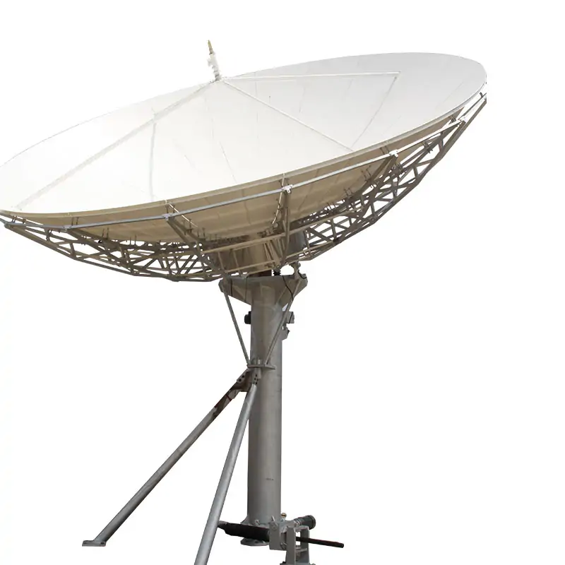
2.4 & 3.0 Meter Receive-Only Antenna Systems
Published 2.4 m and 3.0 m receive-only configurations include model-specific C- and Ku-band performance, mounting and environmental data. Send the required band, feed, site and pointing information for review.
Match the Aperture to the Receive Requirement
Typical use is fixed satellite receive for broadcast, telecommunications and data reception. The pedestals are designed for orbital arc coverage and can be adapted to ground or rooftop installations.
Send Receive RequirementsCatalog Configuration Summary
| Parameter | 2.4 Meter Specifications | 3.0 Meter Specifications |
|---|---|---|
| Frequency Bands | L, X, Ku | L, X, Ku |
| Reflector Material | Aluminum Draw Die Formed | Aluminum Draw Die Formed |
| Construction | Galvanized Steel | Galvanized Steel |
| Feed System | C/Ku Dual Band, Multi-Feed | C/Ku Dual Band, Multi-Feed |
| Wind Survival | 125 mph (200 km/h) published standard; any 180 mph configuration must be confirmed in the quotation | 125 mph (200 km/h) published standard; any 180 mph configuration must be confirmed in the quotation |
| Mount Configuration | Turning-head pedestal, elevation-over-azimuth axis configuration | Elevation-over-azimuth tripod, hot-dipped galvanized after fabrication |
| Environmental Adaptability | Hot-Dipped Galvanizing Option for Coastal Areas | Hot-Dipped Galvanizing Option for Coastal Areas |
Mount configuration is model-specific. The 2.4 m sheet lists a turning-head pedestal with an elevation-over-azimuth axis; the 3.0 m sheet lists an elevation-over-azimuth tripod, hot-dipped galvanized after fabrication.
Both model sheets list survival wind as 125 mph (200 km/h). Any 180 mph high-wind configuration must be confirmed for the selected model and site in the quotation.
2.4 Meter Model
Type: DH 2.4 Meter PF C/ Ku-band Antenna. L-Band,X-Band (Military/WGS) Option.
RF & Antenna Specifications
| C/Ku-band Linear | Receive | Receive |
|---|---|---|
| Frequency, GHz | 3.625-4.2 | 10.95-12.75 |
| Mid-Band Gain, dBi | 37.3 | 47.8 |
| VSWR | 1.4:1 | 1.3:1 |
| 3dBBeam Width, deg | 2.24 | 0.69 |
| Noise Temperature 20 Deg Elevation, K | 47 | 55 |
| 30 Deg Elevation, K | 40 | 46 |
| Port to Port Isolation Rx to Rx (same band),dB | 30 | 30 |
| Axial ratio,dB | 1.5 | |
| Cross-pol on Axis, dB | 25 | 30 |
| Insertion Loss, dB | 0.25 | 0.3 |
| Feed Interface | WR-229 CPR | WR-75 CPR |
| Radiation Pattern Compliance | FCC 25.209, ITU-RS.580-6, | |
| First sidelobe, dB | ≤ -14 | |
| Sidelobe Envelope | 32 – 25 log (1°≤θ<20°) | |
Mechanical Specifications
| Antenna Optics | Prime focus design |
| Refector Aperture | 2.4 Meters (7.8Feet) |
| F/D Ratio | 0.38 |
| Mount Configuration | Turning Head Pedestal Elevation-over Azimuth axis configuration |
| Surface Accuracy (RMS) | 0.5 mm |
| Elevation Travel | 0° to 90 ° Continuous, Including El Angle Adjustment Mark, |
| Azimuth Travel | 0° to 360 ° Continuous, |
| Pol. Travel | ±90°Continuous, |
| Antenna Foundation | Reinforced Concrete Foundation, or Non-penetrating mount (NPM) |
| Shiping Case | 1 Case, Seaworthy Packing |
| Shipping Weight | 187KG, Total volume: 1.1CBM |
| Units/40 ft Container | Quantity 2 Standard 20 ft Quantity 5 Standard 40 ft |
Environmental Performance
| Operational Wind | 45 mph (72 km/h) gusting to 60 mph (97 km/h) |
| Survival Wind | 125 mph (200 km/h), |
| Temperature | -40° C to +50° C |
| Humidity | 0-98% |
Send the Data That Affects the Build
For a non-standard receive feed, review the custom antenna feed systems and antenna feeder networks before the antenna and feed interfaces are fixed.
Email Project Requirements
3.0 Meter Model
Type: DH 3.0 Meter PF C/ Ku-band Antenna. L-Band,X-Band (Military/WGS) Option.
RF & Antenna Specifications
| C/Ku-band Linear | Receive | Receive |
|---|---|---|
| Frequency, GHz | 3.625-4.2 | 10.95-12.75 |
| Mid-Band Gain, dBi | 39.7 | 49.9 |
| VSWR | 1.4:1 | 1.3:1 |
| 3dBBeam Width, deg | 1.7 | 0.55 |
| Noise Temperature 20 Deg Elevation, K | 43 | 48 |
| 30 Deg Elevation, K | 40 | 43 |
| Port to Port Isolation Rx to Rx (same band),dB | 30 | 30 |
| Axial ratio,dB | 1.5 | |
| Cross-pol on Axis, dB | 25 | 30 |
| Insertion Loss, dB | 0.35 | 0.2 |
| Feed Interface | WR-229 CPR | WR-75 CPR |
| Radiation Pattern Compliance | FCC 25.209, ITU-RS.580-6, | |
| First sidelobe, dB | ≤ -14 | |
| Sidelobe Envelope | 32 – 25 log (1°≤θ<20°) | |
Mechanical Specifications
| Antenna Optics | Prime focus design |
| Refector Aperture | 3.0 Meters (9.8Feet) |
| F/D Ratio | 0.375 |
| Mount Configuration | Elevation over Azimuth Tripod, Hot Dipped Galvanized After Fabrication |
| Surface Accuracy (RMS) | 0.5 mm |
| Elevation Travel | 0° to 90 ° Continuous, Including El Angle Adjustment Mark, |
| Azimuth Travel | 360°Continuous, Including Az Angle Adjustment Mark, |
| Pol. Travel | ±90°Continuous, |
| Antenna Foundation | Reinforced Concrete Foundation, or Non-penetrating mount (NPM) |
| Shiping Case | 1 Case, Seaworthy Packing |
| Shipping Weight | 258KG, Total volume: 1.24CBM |
| Units/40 ft Container | Quantity 2 Standard 20 ft Quantity 5 Standard 40 ft |
Environmental Performance
| Operational Wind | 45 mph (72 km/h) gusting to 60 mph (97 km/h) |
| Survival Wind | 125 mph (200 km/h), |
| Temperature | -40° C to +50° C |
| Humidity | 0-98% |
Feed Configuration Is Part of the Antenna Order
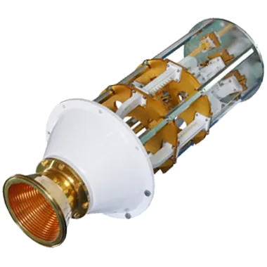
The C/Ku receive tables use WR-229 CPR and WR-75 CPR interfaces. L-band, X-band, multi-feed or other project-specific receive paths should be confirmed with the antenna rather than assumed from the C/Ku table.
Dolph’s custom antenna feed systems cover feed horns, OMTs, filters, diplexers, polarizers and rotary joints. For complete assemblies, see the antenna feeder networks.
For multi-band planning, read how to integrate multiple frequency bands in an antenna feed network. For installation work, see how to connect a waveguide feed to a dish antenna.
Check Feed CompatibilityManufacturing, Measurement and Warranty Information

Manufacturing
The factory page lists CNC machining, turning, waveguide forming and bending, plating, soldering, brazing, assembly and electroforming. Review manufacturing capabilities.
Measurement Support
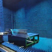
The support page lists RF vector and scalar systems up to 100 GHz, antenna anechoic chambers, high-power transmitters, waveguide calibration, EMI and EMS testing. Review support capabilities.
Company and Warranty
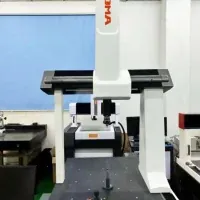
Dolph states that it has operated since 2001. The product warranty covers defective material and workmanship for one year from delivery, subject to the published warranty terms. Review company information.
Use a Different Antenna When the Requirement Changes

Larger Receive-Only System
For a larger fixed receive aperture, review the 6.0 Meter Receive Only Antenna.

For a broader fixed-station comparison, see the earth station antenna range.
Technical Downloads
Use the model datasheets for RF, mechanical, environmental and packing details during technical review.







