
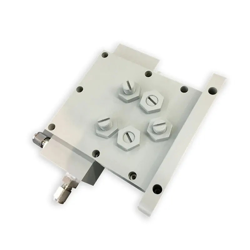
Microwave Water Load for High-Power Industrial Waveguide Systems
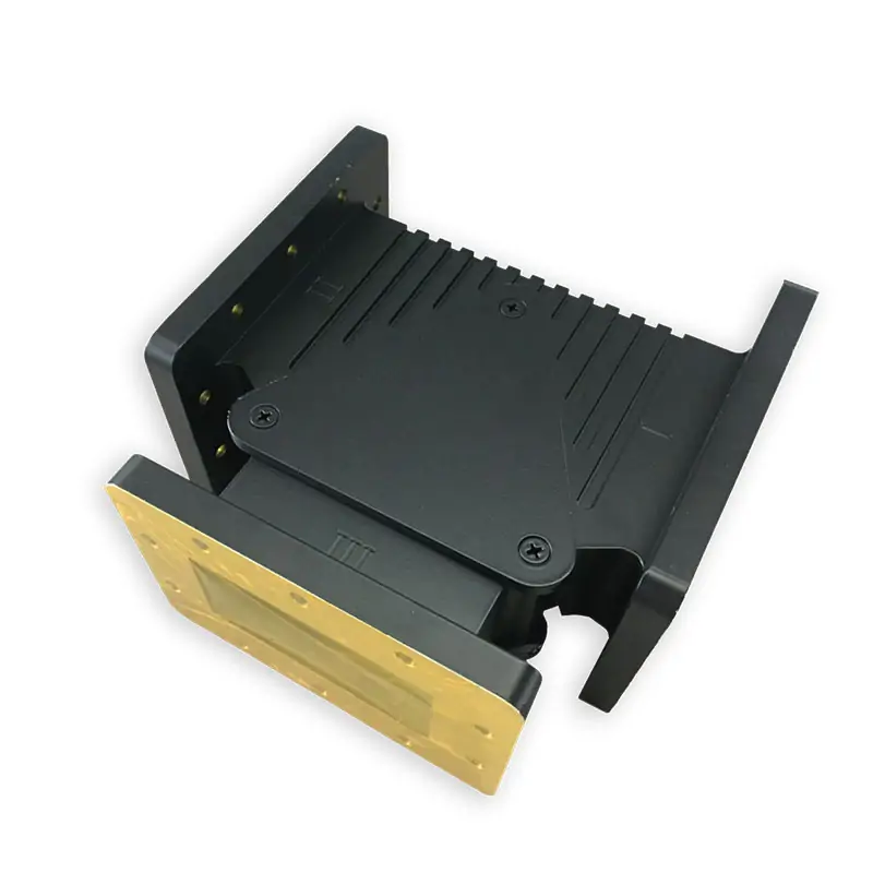
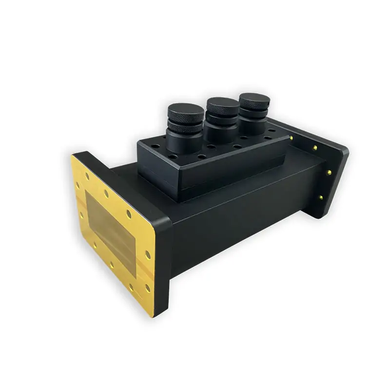
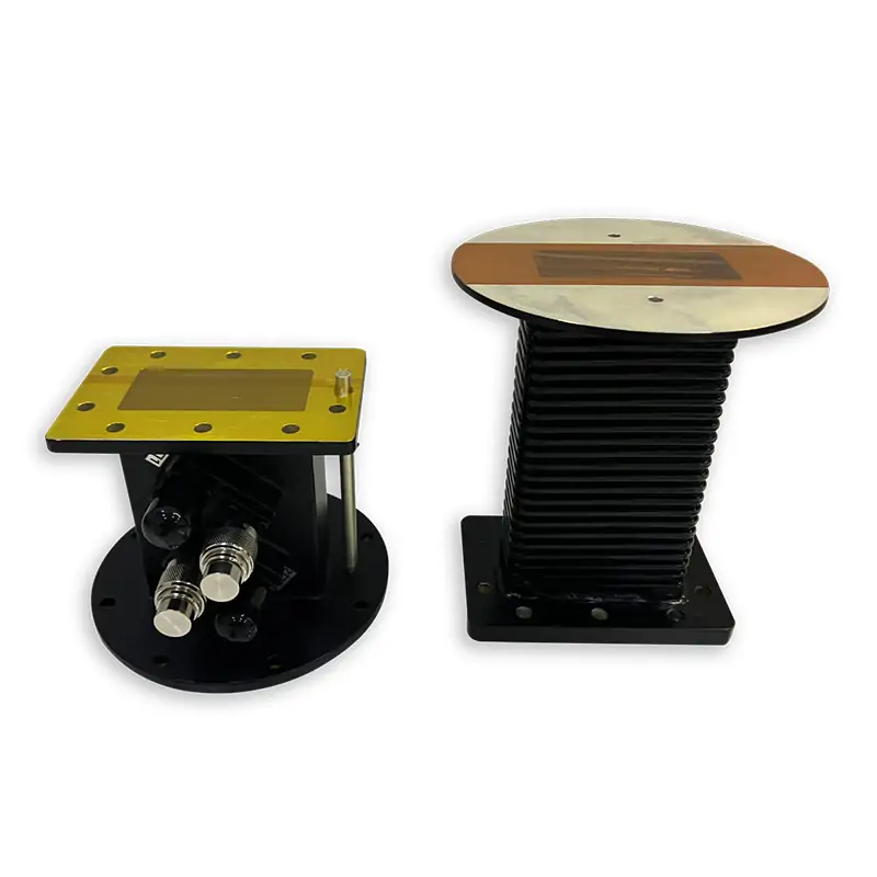
Dolph Microwave water loads absorb reflected or excess microwave power in high-power waveguide systems. The published datasheet lists water-direct models at 915±25 MHz, 1300±25 MHz and 2450±25 MHz across WR975, WR650, WR430, WR340 and WR284, with VSWR 1.2 and model-specific power ratings from 2 kW to 100 kW. Cover and grooved flanges, standard models and customized configurations are available. Send your frequency, power, WR size and flange requirement for model confirmation.
Absorb Reflected Power at the End of Your Waveguide Line
Dolph Microwave Water Load fully absorbs reflected microwave energy with high power handling, light weight and compact size. The datasheet states that cooling type is optional; the published model rows shown below use Water-Direct cooling. Cover and grooved waveguide flanges are listed, and both standard and customized versions can be selected on request.
The datasheet feature block highlights 915 MHz and 2450 MHz, WR340, WR430 and WR975, with 6 kW, 10 kW and up to 20 kW CW. The same published model matrix also lists a 1300±25 MHz WR650 model, WR284 models, and WR975 ratings of 75 kW and 100 kW. Use the model-specific matrix below when selecting a part and confirm the final operating point before order release.
Published Model Matrix
Model family, WR type, frequency, VSWR and handling power are shown as published in the Microwave Water Load datasheet.
| Model | WR Type | Frequency (MHz) | VSWR | Handling Power (kW) |
|---|---|---|---|---|
| DH-9WWHPL915PA… | WR975 | 915±25 | 1.2 | 20 |
| DH-9WWHPL915PA… | WR975 | 915±25 | 1.2 | 75 |
| DH-9WWHPL915PA… | WR975 | 915±25 | 1.2 | 100 |
| DH-14WWHPL1300PA… | WR650 | 1300±25 | 1.2 | 10 |
| DH-22WWHPL2450PA… | WR430 | 2450±25 | 1.2 | 2-3-5-10 |
| DH-22WWHPL2450PA… | WR430 | 2450±25 | 1.2 | 15 |
| DH-26WWHPL2450PA… | WR340 | 2450±25 | 1.2 | 2-3-5-6 |
| DH-26WWHPL2450PA… | WR340 | 2450±25 | 1.2 | 15 |
| DH-32WWHPL2450PA… | WR284 | 2450±25 | 1.2 | 3 |
| DH-32WWHPL2450PA… | WR284 | 2450±25 | 1.2 | 6 |
Cooling, Water Interface and Dimensions
Every row below is kept in the same order as the published model matrix.
| Cooling | Water Flow | Water Pressure | Water Injection | Size (mm) |
|---|---|---|---|---|
| Water-Direct | 3-5L/min | 0.14MPa | Quick Connector | 260*257*213 |
| Water-Direct | 3-5L/min | 0.14MPa | Quick Connector | 260*257*213 |
| Water-Direct | 3-5L/min | 0.14MPa | Quick Connector | 308*257*557 |
| Water-Direct | 3-5L/min | 0.14MPa | Quick Connector | 300*280*150 |
| Water-Direct | 3-5L/min | 0.14MPa | Quick Connector | 170*180*106 |
| Water-Direct | 3-5L/min | 0.14MPa | Quick Connector | 212*161*180 |
| Water-Direct | 3-5L/min | 0.14MPa | Quick Connector | 130*152*95 |
| Water-Direct | 3-5L/min | 0.14MPa | Quick Connector | 170*138*142 |
| Water-Direct | 3-5L/min | 0.14MPa | Quick Connector | 183*335*112 |
| Water-Direct | 3-5L/min | 0.14MPa | Quick Connector | 183*335*112 |
Flange, Finish and Material
| Flange Type | Inside Finish | Body Finish | Material |
|---|---|---|---|
| Cover/Grooved | Iridite per MIL-C-5541 | Anticorrosion Black Painted | Al |
| Cover/Grooved | Iridite per MIL-C-5541 | Anticorrosion Black Painted | Al |
| Cover/Grooved | Iridite per MIL-C-5541 | Anticorrosion Black Painted | Al |
| Cover/Grooved | Iridite per MIL-C-5541 | Anticorrosion Black Painted | Al |
The four finish rows above are displayed exactly as repeated in the published datasheet.
Ordering Information
| DH | Dolph Microwave |
| 26 | Waveguide Type WR340 |
| WWHPL | Water Load |
| 2450 | Freq. 2450 MHz |
| P | Flange Cover |
| M | Flange Grooved |
| A | Material Al |
Send the Data That Determines the Correct Load
Send frequency, input power, waveguide size, flange type, cooling connection and any installation size limit. A drawing or mating-part information helps us check the interface before quotation.


Choose the Adjacent Component by System Function
Use the water load when you need to absorb microwave power. If your requirement is different, choose the component that performs that job in the same industrial microwave line.
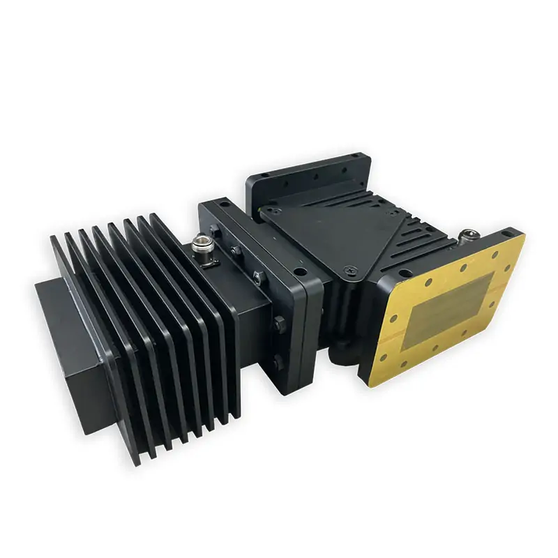
Protect the Source
For one-way power flow and reflected-power protection, review the Microwave Isolator.
Need a Different Power Range or Waveguide Band?
For requirements beyond this Microwave Water Load selection, Dolph Microwave also publishes a separate High Power Water-Cooled Loads range covering WR975 through WR28, with model-specific average power ratings up to 150 kW.
For a complete 915 MHz or 2450 MHz industrial microwave line, review the Custom Industrial Microwave Components page. The site also documents 915 MHz and 2450 MHz industrial waveguide components and waveguide components for microwave plasma applications.
Technical Files and Engineering References
Use the original files for procurement review, flange confirmation and supplier qualification.
Confirm the Model Before You Order
Send your frequency, power, WR size, flange, water connection and required dimensions. Dolph Microwave can check the published model or review a customized configuration for your waveguide line.







