
Keep the pressure in.
Keep the RF path open.
Need to seal a WRD waveguide without breaking the signal path? Start with your waveguide size and frequency range, then check the matching flange, pressure and power figures in the model table. If your installation uses a custom flange or a vacuum boundary, send us the mating drawing.
13 listed models · WRD840–WRD180 · specifications vary by model
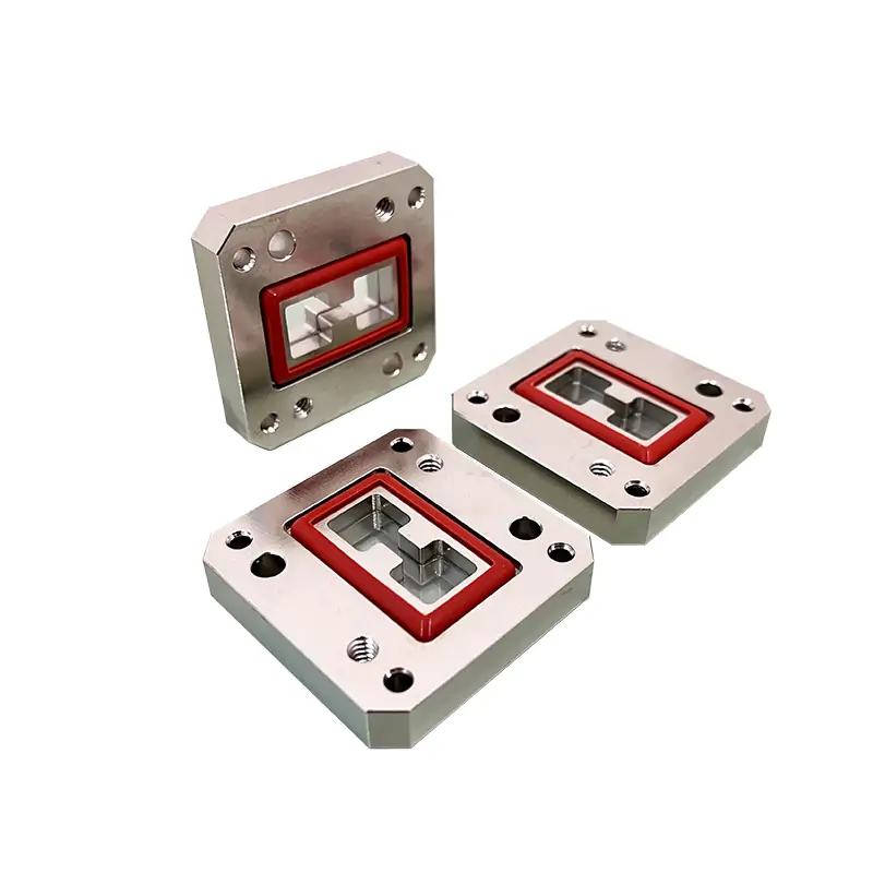
Start with the waveguide you already have.
A WRD size alone does not tell us which flange face you need. The table below gives the exact cover and grooved flange codes for each size. Match those codes to your adjoining section, or share its drawing so we can check the interface.
Give the lowest and highest frequency your equipment uses.
Tell us the pressure difference and the air, gas or other medium.
State average power and any peak-power or duty-cycle requirement.
Confirm both mating flanges, thickness and available space.
Find your exact WRD model.
| Model | Freq. range (GHz) | WG size | VSWR max. | Pressure (PSIG) | Avg power (W) | Window material | Flange / cover | Flange / grooved | Material | Finish | DWG | STEP |
|---|---|---|---|---|---|---|---|---|---|---|---|---|
| DH-840DRWPW… | 0.84-2.0 | WRD840 | 1.15:1 | Up to 45 | Up to 1000 | Teflon/Fiberglass/Ceramics | FPWRD840U24 | FMWRD840U24 | Al/Cu | Chromate/Painted | DWG ↗ | STEP ↗ |
| DH-150DRWPW… | 1.5-3.6 | WRD150 | 1.15:1 | Up to 45 | Up to 1000 | Teflon/Fiberglass/Ceramics | FPWRD150D24 | FMWRD150D24 | Al/Cu | Chromate/Painted | DWG ↗ | STEP ↗ |
| DH-200DRWPW… | 2.0-4.8 | WRD200 | 1.15:1 | Up to 45 | Up to 1000 | Teflon/Fiberglass/Ceramics | FPWRD200D24 | FMWRD200D24 | Al/Cu | Chromate/Painted | DWG ↗ | STEP ↗ |
| DH-250DRWPW… | 2.6-7.8 | WRD250 | 1.15:1 | Up to 45 | Up to 1000 | Teflon/Fiberglass/Ceramics | FPWRD250D30 | FMWRD250D30 | Al/Cu | Chromate/Painted | DWG ↗ | STEP ↗ |
| DH-350DRWPW… | 3.5-8.2 | WRD350 | 1.15:1 | Up to 45 | Up to 1000 | Teflon/Fiberglass/Ceramics | FPWRD350D24 | FMWRD350D24 | Al/Cu | Chromate/Painted | DWG ↗ | STEP ↗ |
| DH-475DRWPW… | 4.75-11.0 | WRD475 | 1.15:1 | Up to 45 | Up to 1000 | Teflon/Fiberglass/Ceramics | FPWRD475D24 | FMWRD475D24 | Al/Cu | Chromate/Painted | DWG ↗ | STEP ↗ |
| DH-500DRWPW… | 5.0-18.0 | WRD500 | 1.15:1 | Up to 45 | Up to 1000 | Teflon/Fiberglass/Ceramics | FPWRD500D36 | FMWRD500D36 | Al/Cu | Chromate/Painted | DWG ↗ | STEP ↗ |
| DH-580DRWPW… | 5.8-16.0 | WRD580 | 1.15:1 | Up to 45 | Up to 1000 | Teflon/Fiberglass/Ceramics | FPWRD580D28 | FMWRD580D28 | Al/Cu | Chromate/Painted | DWG ↗ | STEP ↗ |
| DH-650DRWPW… | 6.5-18.0 | WRD650 | 1.15:1 | Up to 45 | Up to 800 | Teflon/Fiberglass/Ceramics | FPWRD650D28 | FMWRD650D28 | Al/Cu | Chromate/Painted | DWG ↗ | STEP ↗ |
| DH-700DRWPW… | 7.0-18.5 | WRD700 | 1.15:1 | Up to 45 | Up to 800 | Teflon/Fiberglass/Ceramics | FPWRD700D26 | FMWRD700D26 | Al/Cu | Chromate/Painted | DWG ↗ | STEP ↗ |
| DH-750DRWPW… | 7.5-18.0 | WRD750 | 1.15:1 | Up to 45 | Up to 800 | Teflon/Fiberglass/Ceramics | FPWRD750D24 | FMWRD750D24 | Al/Cu | Chromate/Painted | DWG ↗ | STEP ↗ |
| DH-110DRWPW… | 11.0-26.5 | WRD110 | 1.15:1 | Up to 45 | Up to 800 | Teflon/Fiberglass/Ceramics | FPWRD110C24 | FMWRD110C24 | Al/Cu | Chromate/Painted | DWG ↗ | STEP ↗ |
| DH-180DRWPW… | 18.0-40.0 | WRD180 | 1.15:1 | Up to 45 | Up to 800 | Teflon/Fiberglass/Ceramics | FPWRD180C24 | FMWRD180C24 | Al/Cu | Chromate/Painted | DWG ↗ | STEP ↗ |
On a phone, swipe the table sideways. Each DWG / STEP link requests the drawing for that exact model; a verified direct download URL is not available in the source content.
Not sure which row fits? Email us ↗What can be specified for your build?
Keep the flange code with the request.
The published options include flat/cover and grooved flanges. The FPWRD… and FMWRD… designations in the table are different for each WRD size; use the exact code rather than writing only “standard flange.”
- Window: Teflon / Fiberglass / Ceramics, as shown in all model rows.
- Body / flange: Al/Cu (aluminum or copper construction is described in the source).
- Finish: Chromate/Painted in the table; source also mentions iridite, silver plating, Surtec protection and custom coatings.
- Other requests: Pressure gauges, non-standard waveguide sizes, special paint colors and coatings are described as options to discuss.
- Vacuum: The source recommends ceramic or quartz. Quartz is not listed in the 13 standard table rows; check availability for your WRD model before specifying it.
A different material or finish may change the configuration. Confirm the final choice on the approved drawing.
Example from the original product page
DH-840DRWPW30PMA600
The original guide uses this example and these field descriptions. Confirm the complete orderable suffix with sales rather than constructing a part number from this example alone.
Finish note: please confirm before purchase.
The original page says “Standard units are unpainted” in Additional Notes, but its final Note says all models are “painted flat black.” The model table lists “Chromate/Painted.” Its final Note also says flanges are unplated, polished and Surtec-treated, and other finishes and paint colors are available upon request. Please state the required body and flange finish on the purchase drawing.
Ask for the checks your project needs.
Dolph lists CNC machining, turning, waveguide forming and bending, plating, brazing and assembly on its manufacturing page. Its engineering sourcing page also lists RF measurement support. Tell us which measurements and records your order requires.
- Model-specific VSWR or S-parameter sweep and agreed frequency points.
- Pressure differential, leak-test method and acceptance limit.
- Flange dimensions, drawing revision and inspection records.
- DWG / STEP files and any requested test-report format.
These are items to agree in an RFQ, not a claim that each stock model comes with the same tests or certification.
View published manufacturing capabilities ↗The original model matrix lists maximum VSWR 1.15:1. It does not provide a numerical insertion-loss figure for this WRD series.
Tell us the gas or medium, operating pressure and whether a pressure or leak-test record is needed.
A few things worth checking.
These are the details that most often need an approved drawing or an agreed test scope before a pressure window can be specified.
Can I use the 45 PSIG figure for my complete system?
No. It is the upper limit published for these pressure-window model rows, not a guaranteed operating pressure for the whole waveguide line. Confirm the lowest-rated connected component, the pressure differential and your sealing test.
Does VSWR 1.15:1 tell me the insertion loss?
No. VSWR describes reflections; insertion loss is a separate measurement. This product’s original table provides VSWR but no verified insertion-loss value in dB. Ask for the RF measurement you need.
Can I order a quartz window for vacuum service?
The original notes recommend ceramic or quartz for vacuum-sealed applications, while the standard model table lists Teflon, fiberglass and ceramics. Send the WRD size, pressure conditions and medium to confirm quartz availability and qualification for your build.
Are DWG and STEP files available for my model?
Both file types appear as document options in every original model row. Use the request links in the table to ask for the correct file and revision. We have not substituted unverified download links.
Can you match my existing flange and required finish?
Share your mating drawing or the exact FPWRD / FMWRD flange designation, plus the required body and flange finish. The original page includes different statements about whether standard units are painted, so the approved drawing should settle that detail.
Building the rest of the waveguide line?
Send what you have. We’ll check the configuration.
An existing part number, a marked-up flange drawing or the operating conditions is enough to begin a technical conversation. If you need pricing for a particular quantity, include that too.
Email your RFQ- WRD size and frequency range
- Cover / grooved flange codes
- Pressure differential and medium
- Average / peak power and duty
- Window, body material and finish
- Drawing, quantity and delivery need
- RF and pressure acceptance records
- DWG / STEP file requirements







