
Elliptical-to-Rectangular Geometry
Provides a defined physical transition between non-identical waveguide cross-sections while maintaining the required rectangular output interface.
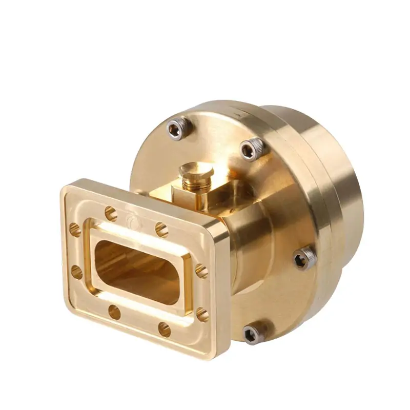
Elliptical to rectangular waveguide adapters are specialized components designed to seamlessly transition microwave signals between elliptical and rectangular waveguide formats. These adapters are critical for integrating systems with different waveguide interfaces, ensuring efficient signal transmission and minimal reflection in various communication and radar applications.
Connect an elliptical waveguide feeder to rectangular waveguide equipment with a configurable adapter family covering a published overall frequency range of 1.7 to 26.5 GHz. The product datasheet lists WR340 through WR62 rectangular waveguide interfaces, 1.05 VSWR, 0.01 dB insertion loss and model-dependent peak-power ratings from 30 to 550 kW.
Standard and customized mechanical configurations are available. Operating band, elliptical interface, rectangular waveguide size, flange type, material, body style and dimensions must be confirmed against the selected part number and approved drawing.
The adapter provides the mechanical and RF transition required when an elliptical feeder must connect to equipment fitted with a rectangular waveguide interface. Typical connection points include antenna feed assemblies, microwave communication links, radar signal paths, satellite ground equipment and laboratory waveguide systems.
Selection is based on the actual operating band and both mating interfaces. The published family range, individual model bands and available mechanical configurations should not be treated as interchangeable values.
Values are reproduced from the published product page and product PDF. Final performance is model- and configuration-dependent.
A reliable selection starts with the complete signal path rather than the rectangular waveguide size alone.
Identify the feeder model, operating band, physical interface and installation orientation.
Converts the physical waveguide format while controlling the transition geometry and mating arrangement.
Match the WR size, IEC or EIA flange designation, flange face and clocking requirements.
Confirm the downstream component, available envelope, power level and environmental requirements.
For the elliptical transmission line itself, review Elliptical Waveguide and Transition . For additional rectangular routing, review Straight Waveguide Sections .
The adapter is specified as an engineered transition, not as a universal mechanical coupling.
Provides a defined physical transition between non-identical waveguide cross-sections while maintaining the required rectangular output interface.
Individual catalog rows are associated with defined frequency ranges, waveguide sizes and flange designations rather than the complete family bandwidth.
The product page states insertion loss better than 0.1 dB, while the model PDF lists 0.01 dB for each displayed catalog row.
Published options include adjustable and adjust-free bodies, cover or grooved flange coding, and different material references according to configuration.
Peak-power values in the published table decrease from 550 kW to 30 kW according to the listed adapter model and waveguide size.
The website summary and product PDF contain different levels of detail. The values below remain separated so that family-level statements are not mixed with individual catalog-model data.
The PDF’s stated overall range extends beyond the frequency rows visible in its model table. For a required band that is not represented by a listed row, submit the exact operating range and mating interfaces for configuration review.
| Model | Frequency Range (GHz) |
VSWR | IL (dB) |
Peak Power (kW) |
WG Type | Interface |
|---|---|---|---|---|---|---|
| DH-26EWALT… | 2.2–2.6 | 1.05 | 0.01 | 550 | WR340 | UAR26/CAR26 |
| DH-32EWALT… | 2.6–3.1 | 1.05 | 0.01 | 550 | WR284 | UDR32/PDR32 |
| DH-40EWALT… | 3.4–4.2 | 1.05 | 0.01 | 310 | WR229 | UDR40/PDR40 |
| DH-48EWALT… | 4.4–5.0 | 1.05 | 0.01 | 190 | WR187 | UDR48/PDR48 |
| DH-48REWALT… | 5.0–6.0 | 1.05 | 0.01 | 150 | WR187 | UAR48/CAR48 |
| DH-70REWALT… | 5.85–7.125 | 1.05 | 0.01 | 100 | WR137 | UDR70/PDR70 |
| DH-84REWALT… | 7.1–8.5 | 1.05 | 0.01 | 80 | WR112 | UAR84/CAR84 |
| DH-100REWALT… | 10.0–11.7 | 1.05 | 0.01 | 80 | WR90 | UDR100/PDR100 |
| DH-120REWALT… | 10.95–12.75 | 1.05 | 0.01 | 50 | WR75 | UBR120/PBR120 |
| DH-140REWALT… | 5.0–6.0 | 1.05 | 0.01 | 30 | WR62 | UAR48/CAR48 |
The DH-140REWALT row is retained exactly as printed in the source PDF. Its published 5.0–6.0 GHz range and UAR48/CAR48 interface do not appear consistent with the displayed WR62 waveguide type. Confirm the complete part number and approved technical data before ordering.
Dimensions are listed by body style and rectangular waveguide entry. Adjustable bodies are shown for most rows, with one adjust-free WR284 entry.
The fifth source column is titled “Weight (kg)” but contains WR waveguide designations. It is identified below as the published WG entry without altering the printed values.
| Body Style | Length (mm) |
Transition Length (mm) |
Width (mm) |
Published WG Entry* | Material |
|---|---|---|---|---|---|
| Adjustable | 260 | 180 | 160 | WR340 | Brass |
| Adjust-free | 260 | 180 | 152 | WR284 | Brass |
| Adjustable | 240 | 170 | 125 | WR229 | Brass |
| Adjustable | 180 | 120 | 106 | WR187 | Brass |
| Adjustable | 180 | 120 | 94 | WR187 | Brass |
| Adjustable | 102 | 69 | 68 | WR137 | Brass |
| Adjustable | 94 | 64 | 60 | WR112 | Brass |
| Adjustable | 86 | 44 | 44 | WR90 | Brass |
| Adjustable | 84 | 44 | 44 | WR75 | Brass |
| Adjustable | 82 | 39 | 39 | WR62 | Brass |
The source PDF shows the example DH-120EWALTPA. The flange suffix is selected according to the required flange face, and the material suffix identifies the chosen material.
“P” and “M” describe alternative flange-face selections. Use the suffix required by the final mating interface rather than combining both flange codes in one part number.
The published sources reference several materials. The required construction should therefore be written into the quotation, part number and approved drawing rather than inferred from a family-level statement.
Material availability and any surface treatment must be confirmed for the selected frequency band, flange arrangement and production configuration.
Supplying the complete interface information reduces the risk of selecting a mechanically compatible but electrically unsuitable configuration.
State the required operating band and whether full-band or narrower-band performance is needed.
Provide the elliptical feeder model, manufacturer reference, cross-section dimensions or mating drawing.
Identify the WR size, IEC or EIA designation, cover or grooved face and any clocking requirement.
State peak and continuous-wave power, pressure requirements and whether RF or environmental sealing is required.
Provide the available length, width, nearby obstructions, mounting direction and adjustable or adjust-free preference.
Specify material preference, operating environment, temperature, finish requirements, project quantity and documentation needs.
Application suitability depends on the selected model, final interface, power level and environmental configuration.
Interface adaptation between elliptical feeder runs and rectangular waveguide radio or antenna equipment.
Connection within antenna feeder and ground-station waveguide assemblies using different cross-section formats.
Transition between feeder sections and rectangular waveguide components in radar transmission or receiving assemblies.
Interface conversion for laboratory fixtures, component evaluation and experimental microwave transmission paths.
Customized mechanical integration where a standard catalog interface does not directly fit the available assembly.
Dolph Microwave states that it was founded in 2001 and operates under an ISO 9001:2015 quality management system. Its published certificate scope covers waveguide component design, manufacture and sale.
Published company capabilities include CNC machining, turning, waveguide forming and bending, soldering and brazing, plating, anodising and passivation.
View ManufacturingPublished resources include RF vector and scalar systems up to 100 GHz, antenna chambers, high-power transmitters, waveguide calibration, EMI/EMS and environmental testing.
View Support CapabilitiesReview the published ISO 9001:2015 certificate and confirm the documentation required for the specific order and delivery.
View ISO CertificateThe test plan and supplied records depend on the product configuration and commercial agreement. Confirm required inspection, RF test data and documentation before the order is released.
Review adjacent product families when the project requires the feeder, additional transition geometry, flange selection or downstream waveguide routing.
Review elliptical feeder products, transitions and related transmission-line information.
View ProductCompare IEC and EIA waveguide and flange designations before defining the mating face.
View ProductAdd rigid rectangular waveguide sections between the adapter and downstream RF equipment.
View ProductConsider a special transition when the required sizes, shapes or mechanical interfaces are nonstandard.
View ProductReview this family when the downstream interface changes from rectangular to circular waveguide.
View ProductDiscuss a coordinated custom RF assembly when one adapter is only part of the required system.
View Custom SolutionsUse the original documents when checking source values, flange designations and related elliptical waveguide information.
No. The PDF states an overall family range of 1.7–26.5 GHz, while the visible table contains individual rows from 2.2 to 12.75 GHz. Bands outside the displayed rows require confirmation against an available or customized configuration.
The product page states insertion loss better than 0.1 dB, while the product PDF lists 0.01 dB for each displayed catalog row. Use the value confirmed for the selected model, operating band and final approved configuration.
The published ordering information includes cover and grooved flange coding, and the product page states that mechanical configurations can be customized. Provide the exact mating flange designation or drawing for review.
The available sources reference copper, aluminum, Cu, brass and an aluminum ordering suffix. Material is therefore configuration-dependent and should be confirmed in the quotation, complete part number and approved drawing.
The source mechanical table lists adjustable bodies for most displayed waveguide sizes and one adjust-free WR284 entry. The required body style should be selected according to installation, tuning and approved mechanical requirements.
Supply the operating band, elliptical feeder information, rectangular waveguide and flange designation, power level, sealing requirement, material, installation envelope, environment, quantity and any mating drawings.
Include the operating frequency, elliptical feeder details, rectangular waveguide size, flange designation, power level and available installation envelope.







