Dolph Microwave
Die-Cut Waveguide Gaskets
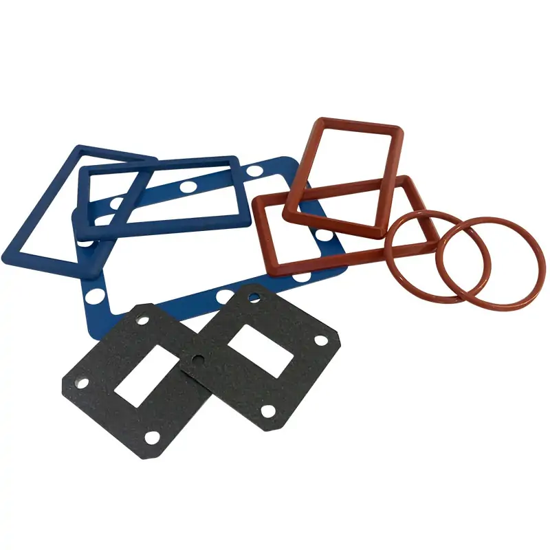
Die-cut waveguide gaskets are flat seals cut to match a waveguide flange face, aperture and bolt pattern. Dolph Microwave’s DH-WFG model table lists conductive silicone gaskets for WR650–WR28 interfaces, with thickness options from 0.5 to 2 mm. Choose the profile from the flange drawing rather than the WR designation alone.
These flat gaskets differ from O-rings and rectangular seals seated in a groove. State whether the joint needs pressure sealing, conductive contact, or both, and identify the mating flange materials and finish. Pressure and RF sealing performance depend on the complete joint, selected material and assembly conditions; the model table does not specify a universal pressure rating.
- Listed thickness range
- 0.5–2 mm
- Standard model table
- WR650–WR28
- Listed model material
- Conductive silicone
These seals are interface accessories for standard waveguide components. Match them to the flange face before selecting the material.
Before you order
Pressure-only or RF and pressure?
Pressure-only seal
The selection notes describe non-conductive silicone or neoprene seals for pressure-sealing duties, usually as O-rings or rectangular profiles in a flange groove. Their suitability depends on the groove geometry, material and operating pressure and temperature.
RF and pressure seal
Conductive gaskets provide an electrical contact path as well as a seal where the joint design requires both functions. The listed flat-gasket models use conductive silicone. Confirm the compound and the required RF leakage and pressure acceptance criteria for the actual flange pair.
Profile and thickness
The table lists thicknesses from 0.5 to 2 mm. Send the aperture, bolt pattern, outside profile and groove dimensions; WR size alone does not define the gasket.
Check the flange size and gasket-fit guide before ordering. The conductive gasket selection guide covers material and profile choices.
For the rest of your setup
Looking for an O-ring profile?
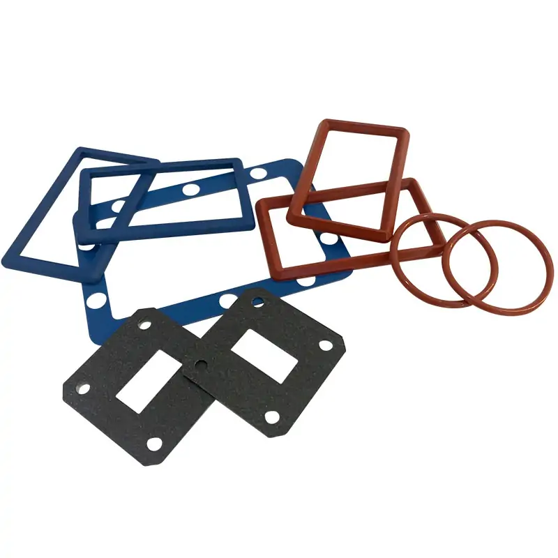
A flat die-cut gasket and a groove-fitting O-ring are different shapes. Compare the gasket and O-ring range if your existing flange uses a recessed seal.
View waveguide gaskets and O-ringsTechnical data
Specifications & dimensions
The original model and flange entries are retained below. Request the material declaration for the quoted compound where RoHS/REACH documentation is required. PDF and STEP labels are not individual download links. Swipe or scroll to see all columns.
| MODEL | WG SIZE | THICKNESS (mm) | FLAT GASKET, DIE CUT FOR CPR/UDR, U/G, UBR, UAR STYLE FLANGES | ELECTRICAL CONDUCTIVITY | MATERIAL | ROHS/REACH | DATASHEET | |||
|---|---|---|---|---|---|---|---|---|---|---|
| DH-14WFGT1… | WR650 | 0.5 to 2 | UDR/CPR650 | Conductive | Silicone | Comply | STEP | |||
| DH-18WFGT1… | WR510 | 0.5 to 2 | UDR/CPR510 | Conductive | Silicone | Comply | STEP | |||
| DH-22WFGT1… | WR430 | 0.5 to 2 | UDR/CPR430 | Conductive | Silicone | Comply | STEP | |||
| DH-26WFGT1… | WR340 | 0.5 to 2 | UDR/CPR340 | Conductive | Silicone | Comply | STEP | |||
| DH-32WFGT1… | WR284 | 0.5 to 2 | UAR32 | UDR/CPR284 | Conductive | Silicone | Comply | STEP | ||
| DH-40WFGT1… | WR229 | 0.5 to 2 | UAR40 | UDR/CPR229 | Conductive | Silicone | Comply | STEP | ||
| DH-48WFGT1… | WR187 | 0.5 to 2 | UAR48 | UDR/CPR187 | Conductive | Silicone | Comply | STEP | ||
| DH-58WFGT1… | WR159 | 0.5 to 2 | UAR58 | UDR/CPR159 | Conductive | Silicone | Comply | STEP | ||
| DH-70WFGT1… | WR137 | 0.5 to 2 | UAR70 | UDR/CPR137 | Conductive | Silicone | Comply | STEP | ||
| DH-84WFGT1… | WR112 | 0.5 to 2 | UG/UBR84 | UDR/CPR112 | Conductive | Silicone | Comply | STEP | ||
| DH-100WFGT1… | WR90 | 0.5 to 2 | PBR100 | UDR/CPR90 | Conductive | Silicone | Comply | STEP | ||
| DH-120WFGT1… | WR75 | 0.5 to 2 | PBR120 | UDR/CPR75 | Conductive | Silicone | Comply | STEP | ||
| DH-140WFGT1… | WR62 | 0.5 to 2 | PBR140 | Conductive | Silicone | Comply | STEP | |||
| DH-180WFGT1… | WR51 | 0.5 to 2 | PBR180 | Conductive | Silicone | Comply | STEP | |||
| DH-220WFGT1… | WR42 | 0.5 to 2 | PBR220 | Conductive | Silicone | Comply | STEP | |||
| DH-260WFGT1… | WR34 | 0.5 to 2 | PBR260 | Conductive | Silicone | Comply | STEP | |||
| DH-320WFGT1… | WR28 | 0.5 to 2 | PBR320 | Conductive | Silicone | Comply | STEP | |||
| Part Number Guide: DH-100WFGT1DC-873 “100”—Waveguide Size | WR90 “WFG”—Gasket Type | Waveguide Flat Gasket “T1″—Thickness | 1 mm, or customer to specify thickness “D/B”—Flanges Style | Rectangle/Square “C-873″— Electrical Conductiovity | Conductive Materials | ||||||||||
| Note: PRESSURE SEAL; or PRESSURE and RF SEAL ? @If a Pressure seal only, then use a NON-CONDUCTIVE Gasket. These are usually Silicon or Neoprene material, O-rings or Rectangles, designed to fit into flange grooves. @If a Pressure and RF seal is required, then use a CONDUCTIVE Gasket. These look similar to the non-conductive gaskets, but are filled with a conductive material, usually copper or silver. The exception is the Die-cut Gasket, which resembles the flange face. | ||||||||||
Materials & ordering options
Technical documents
Questions before ordering
Can you quote from an existing gasket?
Send its dimensions or a drawing, material if known, thickness and clear photographs of the flange face. Include pressure and temperature conditions.
Does the same WR size guarantee the same gasket fit?
No. The flange face, holes, grooves and seal profile also need to match. Supply the full flange designation or drawing.
Related products
Waveguide Flange Standard EIA & IEC
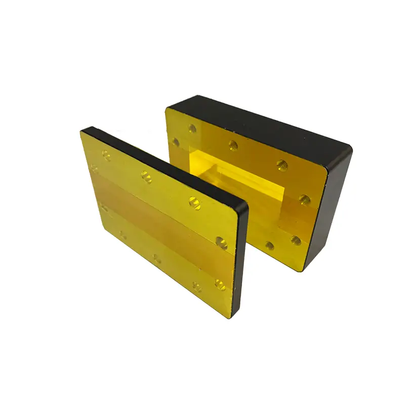
View productTo identify the flange before specifying a seal.
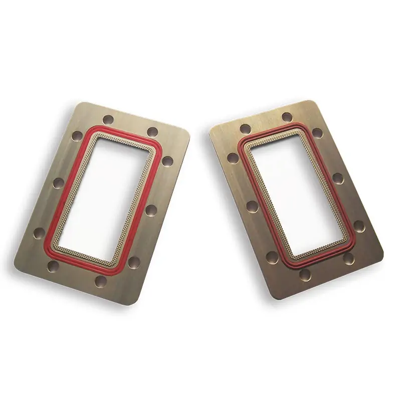
Waveguide Flange Shim
View productFor a separate flange shim requirement.
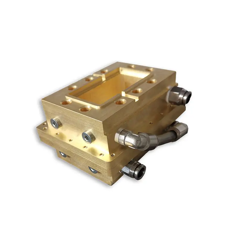
Waveguide Pressure Windows
View productFor a pressure boundary within the waveguide path.
Tell us what you need
Have a model or drawing?
Send the full flange code or mating drawing, aperture and bolt pattern, outside dimensions, thickness and quantity. Specify conductive or non-conductive material, operating pressure and temperature, and any required material declaration or joint leak test. For a replacement, include photographs of both flange faces.