
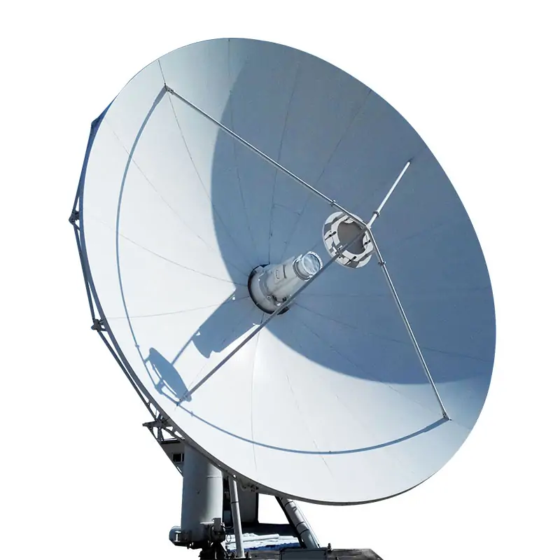
Earth Station Antenna Systems for 2.4–11.3 m and L/S/C/X/Ku/Ka Bands
Configure a fixed earth station antenna by aperture, exact Tx/Rx frequency, polarization, feed ports, reflector type, pedestal, drive and control mode. Dolph Microwave lists antenna options from 2.4 to 11.3 meters or larger, with manual or motorized operation and single- or dual-band configurations. Send your link requirements and site conditions for a matched specification and quotation.
Match the Antenna to the Link, Not Just the Dish Diameter
The product family covers L, S, C, X, Ku and Ka bands with ring-focus or Cassegrain options. The detailed Earth Station Antenna data sheet publishes C-, Ku- and Ka-band Tx/Rx ranges for the 3.7, 4.5, 5.3, 6.2 and 7.3 meter Cassegrain configurations shown below. Final band, aperture and feed combinations are confirmed in the approved specification.
What to Send for an Accurate Antenna Configuration
Earth Station Antenna Options Across the Product Range
Use the dedicated model pages when the project is already narrowed to a specific aperture or operating format. These links stay within Dolph Microwave’s published SATCOM antenna range.
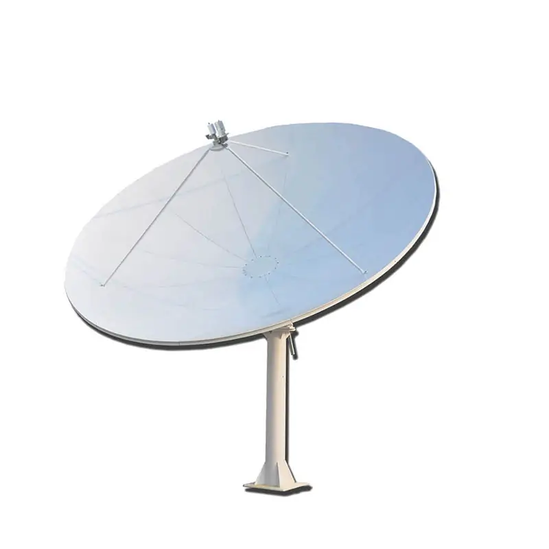 2.4/3.0 Meter Rx Only Antenna Systems
For projects that need satellite reception without a transmit path.
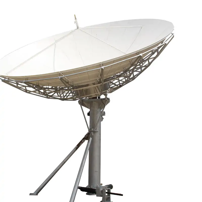
 3.7/4.5 Meter Dual-Reflector System
Dedicated dual-reflector route for 3.7 and 4.5 meter requirements.
 6.2/7.3 Meter Large Size Antenna
For fixed large-aperture requirements in the 6.2 and 7.3 meter class.
RF & Antenna Specifications
The values below reproduce the published Earth Station Antenna data sheet. The frequency rows are shown as Tx and Rx pairs to make the original data easier to read without changing the stated values.
| Aperture | 3.7 Meter | 4.5 Meter | 5.3 Meter | 6.2 Meter | 7.3 Meter |
|---|---|---|---|---|---|
| Reflector Type | Cassegrain | Cassegrain | Cassegrain | Cassegrain | Cassegrain |
| Optional Freq. Band Tx/Rx, GHz |
C-bandTx 5.85~6.725
Rx 3.40~4.20 Ku-bandTx 13.75~14.5
Rx 10.7~12.75 Ka-bandTx 27.5~31.0
Rx 17.7~21.2 | ||||
| VSWR | ≤1.25 | ||||
| Pol. Feature | Circular/Linear | ||||
| Axis Ratio, dB | ≤1.5 | ||||
| Cross Pol Iso, | ≥35 dB (Axis) ≥32dB (-1dB) | ||||
| Tx/Rx Iso, dB | ≥85 | ||||
| First Side Lobe | ≤-14 dB | ||||
| Side Lobe, dB | 29-25logθ (1° ≤θ <20°) | 32-25logθ (20° ≤θ <48°) | -10 dB (θ ≥48°) | ||
| Feed Ports | 2/4 | ||||
| Feed Interface | Wr112 WR75 WR28/42 | WR137/229 WR75 WR28/42 | |||
Mechanical & Drive Specifications
| Aperture | 3.7 Meter | 4.5 Meter | 5.3 Meter | 6.2 Meter | 7.3 Meter |
|---|---|---|---|---|---|
| Pointing Type | Manual/Motorized | Manual/Motorized | Manual/Motorized | Manual/Motorized | Manual/Motorized |
| Antenna Pedestal | Kingpost Pedestal | Kingpost Pedestal | Rotation Pedestal | Kingpost Pedestal | Rotation Pedestal |
| Drive Method | Self-locking mechanical screw jacks | Self-locking mechanical screw jacks Dual motor dual pinion | Self-locking mechanical screw jacks Dual motor dual pinion | ||
| Tracking Method | Step Track with Predictive Tracking | Step Track with Predictive Tracking | Step Track with Predictive Tracking | ||
| Material | aluminum panels fabricated | ||||
| Surface Accuracy | ≤0.35mm RMS. | ||||
| Aligning Method | Self-aligning aluminum reflector-no field alignment | ||||
| Antenna Coverage | Azimuth: ±85°Elevation: 0°~90°Polarization: ±45° | ||||
| Power Supply | 380 VAC 50Hz Three phase 5-WYE | 110/ 220VAC, 47-63Hz European/CE | |||
Environmental Performance

Antenna, Feed and Waveguide Scope Can Be Reviewed Together
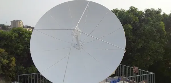
Dolph’s published antenna feed scope includes feedhorns, OMTs, polarizers, filters, diplexers, rotary joints and waveguide sub-systems for prime-focus, offset, ring-focus and Cassegrain arrangements. If your station requires the RF path as well as the reflector system, these interfaces can be reviewed as one project scope.
In a published 3.7 meter Earth Station Antenna delivery and test project, Dolph supplied the antenna together with TX waveguide integration and related RF hardware. The supplied boundary is confirmed project by project.
Choose the Right SATCOM Antenna Route
If no uplink is required, compare the 2.4/3.0 Meter Rx Only Antenna Systems and the 6.0 Meter Receive Only Antenna.
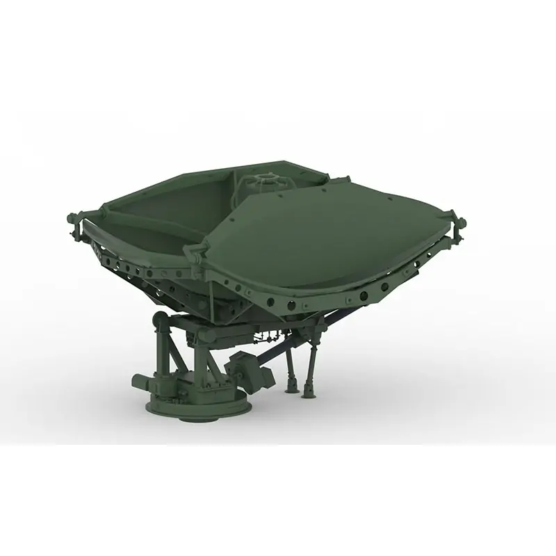
For low- or medium-earth-orbit tracking, use the Low/Medium Earth Orbit Satellite Tracking Antenna. For a relocatable 3.7 meter platform, review the Transportable Trailer Mounted Antenna.
Ordering Information
The published data sheet gives the following ordering example and model-code definitions.
Published Features and Project Uses
Supplier Information You Can Verify
Dolph Microwave states that the company was founded in 2001 and develops microwave components, antenna feed systems and SATCOM-related products.
About Dolph MicrowaveDolph states that its Quality Manual and Quality Procedure use ISO 9001:2015. Certification scope and current certificate status should be checked against the supplier document required for your order.
View Published Quality CertificateDolph’s published warranty covers defects in material and workmanship for one year from delivery, subject to the full warranty terms and exclusions.
Read Terms & ConditionsPublished capabilities include CNC machining, waveguide forming and bending, brazing and assembly, plating, antenna anechoic chambers and environmental testing for microwave component and feed-system work.







