

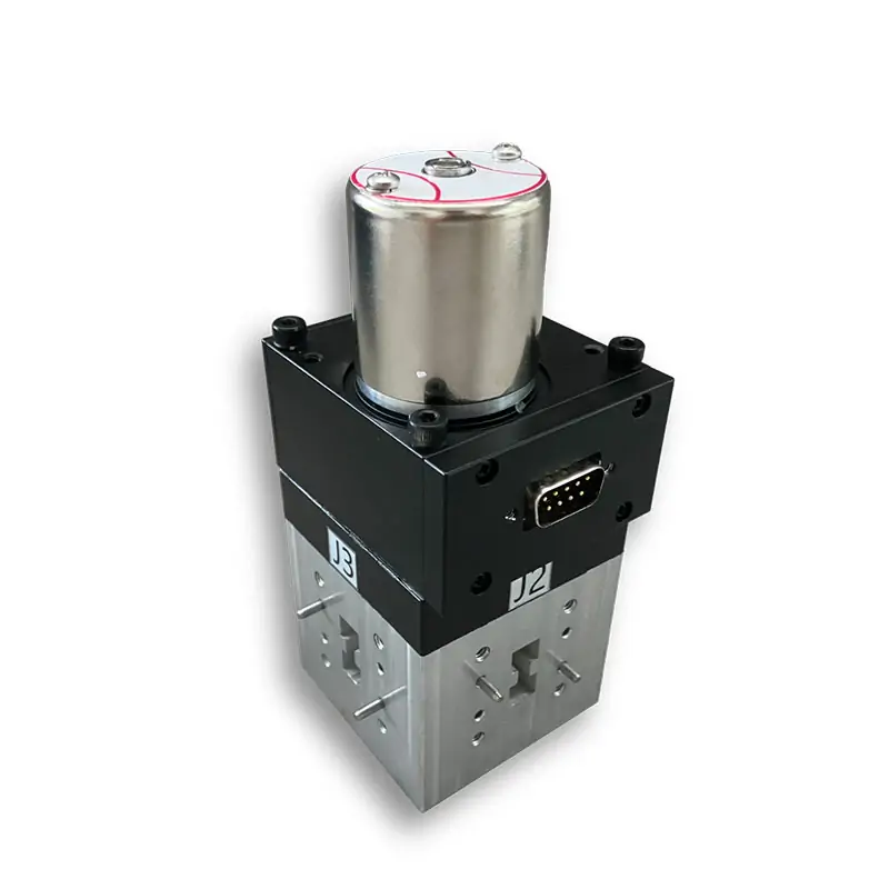
Double-Ridged Waveguide Switches | SPDT & DPDT
Latching double-ridged waveguide switches for the listed WRD840 through WRD180 models. Published bands run from 0.84-2.0 GHz through 18.0-40.0 GHz, with 1.15:1 VSWR, 65 dB isolation, SPDT or DPDT routing, cover or grooved flanges, and 22~32 VDC actuator power.
Send the operating band, WRD size, routing type, flange designation and quantity. We will check the closest published model and any interface changes before quotation.
Choose the Switch Around the Actual RF Path
The final choice is controlled by the complete operating band, matching WRD size, SPDT or DPDT routing, switching time and the mating flange at each port.
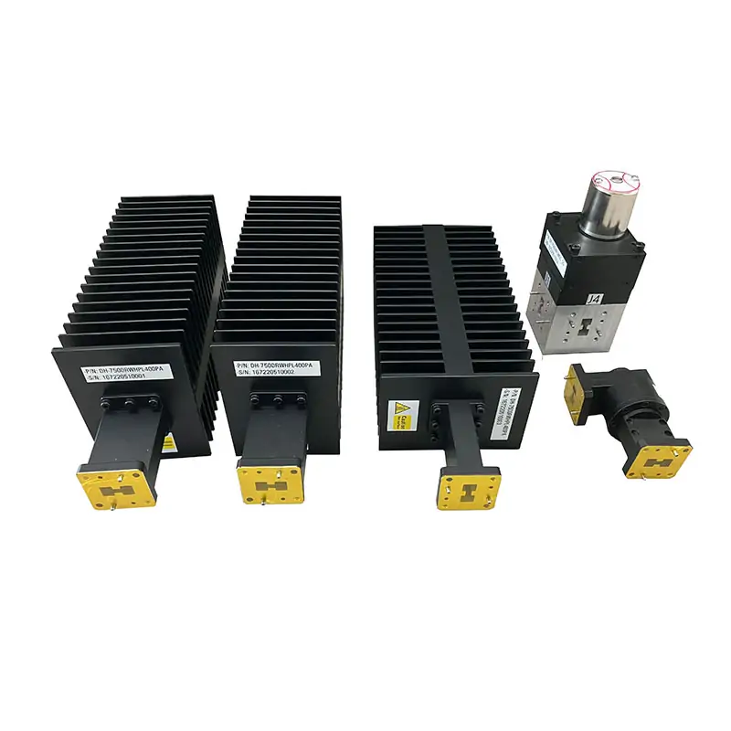
Waveguide Switch Specifications
Match the frequency range, WRD size, switch type, insertion loss, switching time and flange designation to the required interface. The published model data is retained below without reducing the listed fields.
On mobile, scroll the table horizontally. The model column remains visible.
| Model | Frequency Range (GHz) | WG Size | VSWR | IL (dB) | Isolation (dB) | Switch Time (mSec) | Actuator | Switch Type | Voltage (VDC) | Cover Flange | Grooved Flange | Datasheet | 3D Model |
|---|---|---|---|---|---|---|---|---|---|---|---|---|---|
| DH-840DRWDESMD… | 0.84-2.0 | WRD840 | 1.15:1 | 0.2 | 65 | 120 | Latching | DPDT | 22~32 | FPWRD840U24 | FMWRD840U24 | STEP | |
| DH-840DRWESMD… | 0.84-2.0 | WRD840 | 1.15:1 | 0.2 | 65 | 120 | Latching | SPDT | 22~32 | FPWRD840U24 | FMWRD840U24 | STEP | |
| DH-150DRWDESMD… | 1.5-3.6 | WRD150 | 1.15:1 | 0.2 | 65 | 120 | Latching | DPDT | 22~32 | FPWRD150D24 | FMWRD150D24 | STEP | |
| DH-150DRWESMD… | 1.5-3.6 | WRD150 | 1.15:1 | 0.2 | 65 | 120 | Latching | SPDT | 22~32 | FPWRD150D24 | FMWRD150D24 | STEP | |
| DH-200DRWDESMD… | 2.0-4.8 | WRD200 | 1.15:1 | 0.2 | 65 | 120 | Latching | DPDT | 22~32 | FPWRD200D24 | FMWRD200D24 | STEP | |
| DH-200DRWESMD… | 2.0-4.8 | WRD200 | 1.15:1 | 0.2 | 65 | 120 | Latching | SPDT | 22~32 | FPWRD200D24 | FMWRD200D24 | STEP | |
| DH-250DRWDESMD… | 2.6-7.8 | WRD250 | 1.15:1 | 0.3 | 65 | 120 | Latching | DPDT | 22~32 | FPWRD250D30 | FMWRD250D30 | STEP | |
| DH-250DRWESMD… | 2.6-7.8 | WRD250 | 1.15:1 | 0.3 | 65 | 120 | Latching | SPDT | 22~32 | FPWRD250D30 | FMWRD250D30 | STEP | |
| DH-350DRWDESMD… | 3.5-8.2 | WRD350 | 1.15:1 | 0.4 | 65 | 120 | Latching | DPDT | 22~32 | FPWRD350D24 | FMWRD350D24 | STEP | |
| DH-350DRWESMD… | 3.5-8.2 | WRD350 | 1.15:1 | 0.4 | 65 | 120 | Latching | SPDT | 22~32 | FPWRD350D24 | FMWRD350D24 | STEP | |
| DH-475DRWDESMD… | 4.75-11.0 | WRD475 | 1.15:1 | 0.4 | 65 | 120 | Latching | DPDT | 22~32 | FPWRD475D24 | FMWRD475D24 | STEP | |
| DH-475DRWESMD… | 4.75-11.0 | WRD475 | 1.15:1 | 0.4 | 65 | 120 | Latching | SPDT | 22~32 | FPWRD475D24 | FMWRD475D24 | STEP | |
| DH-500DRWDESMD… | 5.0-18.0 | WRD500 | 1.15:1 | 0.4 | 65 | 120 | Latching | DPDT | 22~32 | FPWRD500D36 | FMWRD500D36 | STEP | |
| DH-500DRWESMD… | 5.0-18.0 | WRD500 | 1.15:1 | 0.4 | 65 | 120 | Latching | SPDT | 22~32 | FPWRD500D36 | FMWRD500D36 | STEP | |
| DH-580DRWDESMD… | 5.8-16.0 | WRD580 | 1.15:1 | 0.35 | 65 | 80 | Latching | DPDT | 22~32 | FPWRD580D28 | FMWRD580D28 | STEP | |
| DH-580DRWESMD… | 5.8-16.0 | WRD580 | 1.15:1 | 0.35 | 65 | 80 | Latching | SPDT | 22~32 | FPWRD580D28 | FMWRD580D28 | STEP | |
| DH-650DRWDESMD… | 6.5-18.0 | WRD650 | 1.15:1 | 0.35 | 65 | 80 | Latching | DPDT | 22~32 | FPWRD650D28 | FMWRD650D28 | STEP | |
| DH-650DRWESMD… | 6.5-18.0 | WRD650 | 1.15:1 | 0.35 | 65 | 80 | Latching | SPDT | 22~32 | FPWRD650D28 | FMWRD650D28 | STEP | |
| DH-700DRWDESMD… | 7.0-18.5 | WRD700 | 1.15:1 | 0.35 | 65 | 80 | Latching | DPDT | 22~32 | FPWRD700D26 | FMWRD700D26 | STEP | |
| DH-700DRWESMD… | 7.0-18.5 | WRD700 | 1.15:1 | 0.35 | 65 | 80 | Latching | SPDT | 22~32 | FPWRD700D26 | FMWRD700D26 | STEP | |
| DH-750DRWDESMD… | 7.5-18.0 | WRD750 | 1.15:1 | 0.4 | 65 | 80 | Latching | DPDT | 22~32 | FPWRD750D24 | FMWRD750D24 | STEP | |
| DH-750DRWESMD… | 7.5-18.0 | WRD750 | 1.15:1 | 0.4 | 65 | 80 | Latching | SPDT | 22~32 | FPWRD750D24 | FMWRD750D24 | STEP | |
| DH-110DRWDESMD… | 11.0-26.5 | WRD110 | 1.15:1 | 0.4 | 65 | 80 | Latching | DPDT | 22~32 | FPWRD110C24 | FMWRD110C24 | STEP | |
| DH-110DRWESMD… | 11.0-26.5 | WRD110 | 1.15:1 | 0.4 | 65 | 80 | Latching | SPDT | 22~32 | FPWRD110C24 | FMWRD110C24 | STEP | |
| DH-180DRWDESMD… | 18.0-40.0 | WRD180 | 1.15:1 | 0.4 | 65 | 80 | Latching | DPDT | 22~32 | FPWRD180C24 | FMWRD180C24 | STEP | |
| DH-180DRWESMD… | 18.0-40.0 | WRD180 | 1.15:1 | 0.4 | 65 | 80 | Latching | SPDT | 22~32 | FPWRD180C24 | FMWRD180C24 | STEP |
Configuration and Ordering Details
The linked product catalog identifies motor-driven double-ridged switch configurations, SPDT or DPDT routing, cover or grooved flanges, aluminium or copper material options, and actuator options including TTL Logic, Self Cut Off and Window Indicator.
Catalog Part-Number Logic
Have a Fixed Interface or Existing Part to Match?
Send the existing part number, mating flange, installation envelope or drawing with the RF requirements. We can review a catalog model first, then check whether a modified interface or custom assembly is needed.
Build the Switch Into the Rest of the RF Path
Keep the WRD size and flange interface consistent with the adjoining components. For a complete double-ridged path, browse the double-ridged waveguide product family or send the full routing drawing for an integrated review.
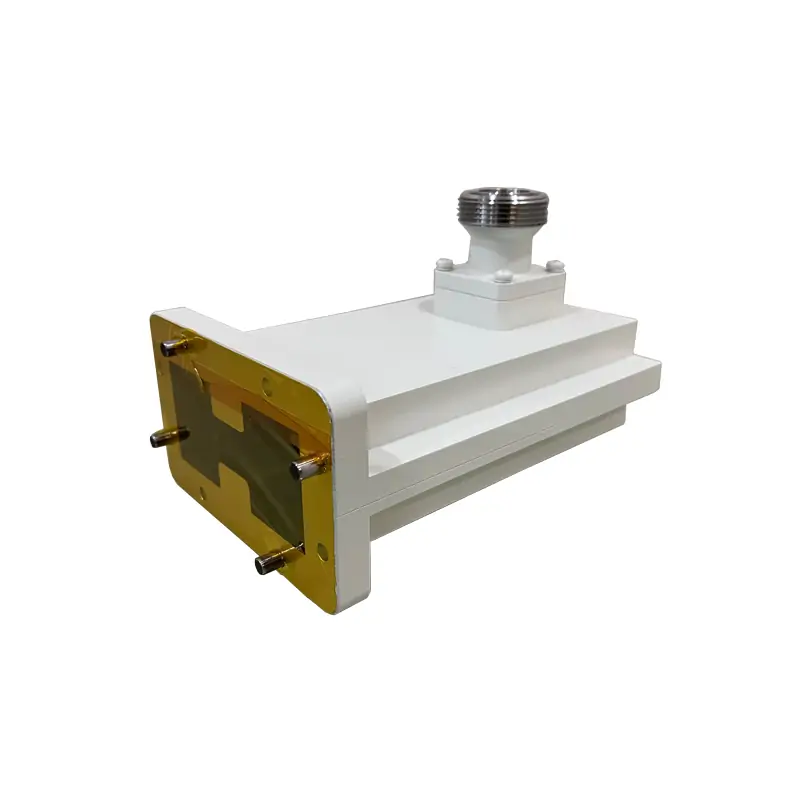
Waveguide to Coaxial Interface
When the switched path must transition to coax, match the required band, connector and flange with a high-power waveguide coaxial adapter.
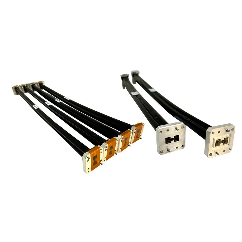
Installation Flexibility
For alignment, movement or installation tolerance, select a flexible waveguide by size, length, type and flange arrangement.
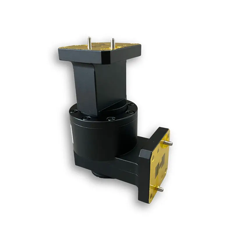
Continuous Rotation
For continuous mechanical rotation rather than discrete switching, use a waveguide rotary joint matched to the channel and interface.
Rigid routing can be completed with double-ridged waveguide bends and double-ridged straights and transitions where the installation drawing calls for fixed geometry or a change in interface.
Manufacturing, Verification and Supplier Records
Dolph Microwave manufactures waveguide components in Xi’an. Published factory capability includes CNC milling and turning, waveguide forming and bending, brazing, plating, anodising/passivation and dimensional inspection. In-house RF vector and scalar measurement is listed up to 100 GHz.
For supplier review, see the manufacturing capabilities and the waveguide components sourcing page.



Send Enough Information for a Usable Quote
A model check is faster when the RF and mechanical interfaces arrive together. Include the items that affect the final part and drawing.
Add Project Limits When They Matter
If the switch is part of a high-power, pressurized or environmentally controlled line, include those operating conditions instead of relying on the model family alone.
For high-power requirements, use the waveguide power-handling guide to identify the CW, peak-power, pressure and cooling information that should accompany the RFQ.
Waveguide Switch Downloads
Use the product-series document for switch selection and the flange reference document to check the required double-ridged flange designation.
Waveguide Switches
Review the product-series switch data and ordering information.
Double-Ridged Flange Type Designations
Check the mating flange dimensions and designation before final release.







