A waveguide pressure inlet should be selected as part of a complete pressurization system, not as an isolated threaded port. The inlet must match the pressurizing gas connection, waveguide size, flange interface, seal arrangement, operating pressure, relief path, tubing capacity, and moisture-control method.
For most microwave transmission systems, “gas connection” refers to a connection for clean, dry air or an approved inert gas such as nitrogen. It does not normally mean a combustible fuel-gas connection. The gas source must be clean enough that it does not introduce oil, water, particles, or reactive contaminants into the waveguide.
The correct selection sequence is:
- Identify the waveguide size, frequency range, flange designation, and pressure boundary.
- Confirm the inlet thread, connector type, tube outside diameter, and gas-source interface.
- Establish the normal operating pressure and the rating of every pressure-containing component.
- Select the regulator, gauge, alarm, and pressure-relief arrangement.
- Define the required purge flow, leakage allowance, and gas dew point.
- Verify the assembly by leak testing, pressure monitoring, and RF measurements.
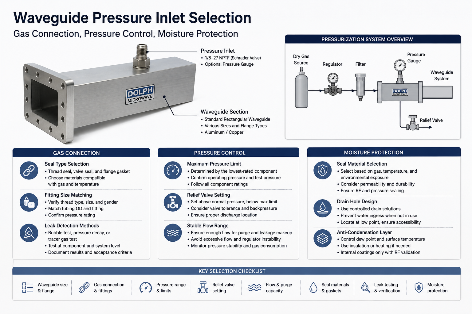
Dolph Microwave supplies standard rectangular waveguide pressure inlet sections with multiple waveguide sizes, flange types, materials, section lengths, and optional pressure-monitoring arrangements. The published model table includes 1/8-27 NPTF Schrader-valve configurations for a range of standard waveguide sizes. Custom projects should still be reviewed against the approved drawing because connector, pressure, flange, and material requirements may differ from the standard table.[1]
| Selection Input | What Must Be Confirmed | Risk If It Is Missed |
|---|---|---|
| Waveguide interface | WR size, frequency range, flange designation, groove and gasket geometry | RF mismatch, flange leakage, incorrect bolt pattern |
| Gas connection | Thread family, nominal size, gender, valve type and tubing outside diameter | Cross-threading, leakage or restricted flow |
| Pressure envelope | Normal pressure, alarm limits, relief setting and lowest component rating | Overpressure, window damage or repeated alarm cycling |
| Moisture control | Gas dew point, sealing materials, purge method and cold-surface temperature | Internal condensation, corrosion and unstable high-power performance |
| Verification | Leak-test method, test pressure, stabilization time and RF acceptance criteria | Undetected leakage or a mechanically sound but electrically unsuitable assembly |
Table of Contents
Gas Connection
The gas connection determines how reliably the pressure inlet can receive dry gas from a dehydrator, regulated cylinder, compressor-dryer package, or central pressurization manifold. A suitable connection must provide both mechanical compatibility and a controlled pressure boundary without disturbing the RF path.
Seal Type Selection
Start by separating the sealing functions. A pressure inlet may require a thread seal at the gas fitting, an elastomeric seal around a valve or plug, and a flange gasket between adjacent waveguide components. These seals do not necessarily use the same construction or material.
At the waveguide flange, determine whether the gasket is required only to contain pressure or must also contribute to RF continuity and electromagnetic shielding. Dolph Microwave’s waveguide gasket and O-ring guidance distinguishes between non-conductive gaskets for pressure sealing and conductive gaskets where both pressure and RF sealing are required.[2]
- Pressure-only seal: A non-conductive elastomeric O-ring or shaped gasket may be suitable when the flange design provides the required metal-to-metal RF contact independently of the gasket.
- Pressure and RF seal: A conductive elastomer or conductive die-cut gasket may be required when the interface design depends on the gasket for both environmental sealing and electrical continuity.
- Thread seal: The sealing method must be compatible with the actual thread specification. A taper-thread sealant must not be treated as a substitute for mismatched or damaged threads.
- Valve seal: Schrader valves, check valves, gauges and quick-connect fittings should retain their manufacturer-approved internal seals. Unapproved lubricants or compounds can contaminate the gas path.
Dolph’s standard pressure inlet table identifies 1/8-27 NPTF on listed rectangular-waveguide models. NPTF is a dryseal tapered thread system. ASME B1.20.3 explains that dryseal threads are designed to form pressure-tight joints through controlled metal contact when the mating threads conform to the required form and tolerances. A compatible lubricant or sealant may still be used where appropriate to reduce galling, but it should not be used to compensate for incorrect thread geometry.[3]
When a sealing compound is permitted, apply only the amount and location specified by the fitting manufacturer. Excess tape or paste can be cut from the thread during assembly and enter the waveguide or regulator. Particles inside the waveguide can create contamination, RF discontinuities, or high-field concentration points.
Before approval, record the following seal information:
- Seal type and part number
- Elastomer or conductive filler material
- Gas compatibility
- Minimum and maximum service temperature
- Required compression or groove dimensions
- Expected replacement interval
- Compatibility with the flange metal and surface finish
Fitting Size Matching
Nominal fitting size alone is not enough. The purchasing specification should identify the thread standard, nominal size, gender, sealing method, valve type, tubing outside diameter, fitting material, and pressure rating.
For example, 1/8 NPTF and G1/8 are not interchangeable. NPTF is a tapered dryseal pipe thread, while G threads are normally parallel pipe threads that depend on a separate sealing face, washer, bonded seal, or O-ring. A fitting may appear to engage for several turns while still having incorrect pitch, flank angle, taper, or sealing geometry.
| Interface Item | Required Check |
|---|---|
| Thread designation | Confirm NPT, NPTF, BSPT, BSPP/G, metric or another specified system |
| Nominal size | Confirm the full designation instead of measuring only the visible outside diameter |
| Connection gender | Verify male and female orientation on both the inlet and the mating fitting |
| Tubing size | Match actual tubing OD and wall thickness to the compression or push-in fitting |
| Flow passage | Check the minimum internal bore through the valve, fitting and tube |
| Material | Review aluminum, brass, stainless steel, copper and coating compatibility |
| Pressure rating | Use the rating at the project temperature, not only the room-temperature catalog value |
The fitting must also be mechanically suitable for the pressure inlet section. A threaded part should not project into the waveguide aperture, create an internal burr, or alter the designed cross-section. The port boss and wall thickness must provide sufficient thread engagement without introducing a weak section into the waveguide body.
For a standard Dolph pressure inlet, confirm the required waveguide size, flange code, inlet connection, section length, material and optional gauge against the model table and final drawing. Dolph currently lists short spacer-style inlets and longer pressurizing sections, allowing the gas connection to be positioned according to the installation envelope.[1]
The gas line between the pressure inlet and the regulator should be routed to avoid sharp bends, unsupported weight, vibration loading and water traps. Where flexible tubing is used, verify its minimum bend radius, environmental rating and pull-out resistance. A drip loop or downward approach may help prevent external water from running directly toward the fitting.
Leak Detection Methods
A pressure inlet should be tested at both component level and installed-system level. No single test method covers every leakage condition.
The three most useful methods are:
- Bubble-emission testing: Apply an approved leak-detection liquid to threaded joints, valve stems, plugs, gauge connections and flange edges while the system is under a controlled test pressure. ASTM E515 describes liquid-application and immersion bubble-emission techniques for locating leaks.[4]
- Pressure-decay testing: Pressurize the isolated volume, allow pressure and temperature to stabilize, then monitor pressure over a defined period. This method evaluates the complete enclosed volume but must account for gas-temperature changes.
- Tracer-gas testing: Use helium or another approved tracer with suitable detection equipment when the specified leakage limit is below the practical sensitivity of bubble or ordinary pressure-decay testing.
A practical installation test sequence is:
- Confirm that the test medium is compatible with every component.
- Verify the approved test pressure and the lowest pressure rating in the test boundary.
- Increase pressure gradually using a regulated source.
- Isolate the gas source and allow the assembly to reach thermal equilibrium.
- Apply leak-detection liquid to accessible joints and observe for bubble formation.
- Record pressure, ambient temperature and elapsed time for the pressure-decay check.
- Repair any identified leak, replace damaged seals and repeat the test.
- Remove test residue and confirm that no liquid has entered the RF passage.
Pressure decay should not be interpreted without temperature data. Cooling after rapid filling can produce an apparent pressure loss even when the system is sealed. Solar heating can produce the opposite result. For repeatable records, use a defined stabilization time, calibrated gauge or transducer, known test volume, and consistent test duration.
Acceptance criteria must come from the project specification, customer drawing, applicable equipment manual, or an agreed leakage-rate requirement. Statements such as “no pressure loss” or “bubble tight” are incomplete unless the test pressure, observation time, instrument resolution and allowable leakage are also defined.
Pressure Control
Waveguide pressurization is intended to maintain a controlled internal atmosphere. It should not subject the transmission line to the highest pressure that an individual inlet can survive. Normal operating pressure is usually established by the complete transmission system, dehydrator or regulated gas source, environmental conditions, and pressure-window design.
Maximum Pressure Limit
The system pressure limit is set by the lowest-rated component inside the complete pressure boundary. Review the pressure inlet, waveguide sections, flexible waveguide, pressure windows, gaskets, rotary joints, switches, couplers, gauges, valves, tubing, fittings and terminations.
Dolph’s published standard rectangular waveguide pressure inlet table currently lists 45 PSIG for its displayed WR650 through WR28 models. Dolph’s waveguide pressure-window table also provides model-specific pressure data. These component values are useful for preliminary screening, but they do not automatically establish the allowable operating pressure of the complete assembled line.[1][5]
The procurement drawing should distinguish between:
- Normal operating pressure: The intended regulated pressure during service
- Operating pressure range: The acceptable control band, including regulator cycling
- Low-pressure alarm: The point indicating excessive leakage or gas-supply failure
- High-pressure alarm: The point indicating regulator or control malfunction
- Relief-valve set pressure: The pressure at which overpressure protection begins to operate
- Maximum allowable pressure: The maximum permitted pressure for the defined assembly and temperature
- Leak-test pressure: The controlled pressure used for the specified verification procedure
- Proof or qualification pressure: A separately defined engineering or qualification value that must not be assumed from the operating pressure
Do not treat marketing-level family descriptions as a substitute for model-specific data. The final purchase document should state the pressure rating, temperature range, test method and acceptance requirement for the exact part number. For a custom assembly, request an approved dimensional drawing and pressure declaration before production.
Operating significantly above the pressure needed for moisture exclusion does not automatically improve reliability. It increases mechanical loading, gas consumption and the consequences of regulator failure, while potentially exposing weaker windows, flexible sections or seals.
Relief Valve Setting
The pressure-relief device protects the pressure boundary if the regulator, heater, gas source, control valve or environmental temperature causes the internal pressure to rise above the permitted range. ASME describes pressure-relief devices as a means of preventing pressurized equipment from exceeding its maximum allowable working pressure.[6]
The relief setting should therefore be:
- Above the highest expected normal operating pressure and normal regulator fluctuation
- Below the lowest maximum allowable pressure in the protected volume
- Adjusted for valve tolerance, accumulation, reseating behavior and downstream backpressure
- Capable of passing the maximum credible inflow from the regulator or gas source
A universal percentage should not be applied without reviewing the selected relief-valve design and applicable pressure code. Proportional relief valves, pop-action safety valves and pressure-regulating relief devices have different opening and reseating characteristics.
For a low-pressure waveguide system, an oversized or unsuitable relief valve can become unstable, leak continuously, or cycle near the normal operating pressure. Select a device intended for the required low-pressure range and gas service. The manufacturer’s flow curve should demonstrate that the valve can discharge the credible failure flow before the protected system exceeds its allowable pressure.
The relief outlet should be:
- Directed to a safe location
- Protected from rain, insects and blockage
- Positioned so discharged gas cannot re-enter the waveguide or equipment enclosure
- Installed without excessive backpressure
- Accessible for inspection and functional testing
After adjustment, secure and label the relief setting. Record the valve model, serial number, set pressure, test medium, test date and calibration status. Field personnel should not increase the setting simply to stop nuisance venting; repeated venting normally indicates incorrect regulator settings, thermal expansion, leakage into the system, or an undersized relief path.
Stable Flow Range
Stable pressurization depends on both pressure and flow. Pressure keeps humid ambient air from entering through small leakage paths, while flow is needed for initial purging and for replacing gas lost through normal leakage or control-system bleed.
There is no single flow rate that is correct for every waveguide pressure inlet. The required capacity depends on:
- Total internal waveguide volume
- Number of branches and pressurized components
- Specified purge time
- Maximum expected leakage rate
- Regulator and dehydrator control method
- Tubing diameter, length and pressure drop
- Minimum operating pressure at the most remote point
- Ambient temperature and altitude
A preliminary purge-flow relationship can be expressed as:
Required purge flow = required volume exchanges × internal system volume ÷ available purge time
All volumes and flow rates must be compared at consistent reference conditions. The number of required volume exchanges should come from the approved commissioning procedure, humidity measurement or gas-quality validation rather than an unsupported rule of thumb.
For steady pressure maintenance:
Supply capacity must exceed maximum system leakage plus intentional control bleed, with an engineering margin.
Too little flow causes slow purging, low-pressure alarms and possible moisture ingress at remote branches. Excessive flow can create regulator instability, unnecessary gas consumption, local cooling and high gas velocity. It can also mask a significant leak because the pressure source continuously replaces the escaping gas.
A pressurization system should not be judged only by whether the gauge reaches its setpoint. Evaluate:
- Time required to reach operating pressure
- Pressure variation during regulator cycling
- Compressor or valve duty cycle
- Pressure at the remote end of the waveguide
- Gas consumption over a defined period
- Humidity or dew-point trend after purging
CommScope describes transmission-line dehydrator operation in which the compressor runs only when required to maintain line pressure. This illustrates an important design principle: a sealed system should normally require intermittent makeup rather than uncontrolled continuous high flow.[7]
If the source operates almost continuously after the system has been purged, investigate flange seals, threaded fittings, pressure windows, flexible sections and drain features. Increasing flow without finding the leakage path transfers the problem to the compressor or gas supply.
Moisture Protection
Moisture protection requires more than installing a sealed pressure inlet. The internal gas must be sufficiently dry, the pressure boundary must resist humid-air ingress, and the coldest internal surface must remain above the gas dew point during operation and shutdown.
A practical moisture-control specification should state:
- Approved pressurizing gas
- Maximum gas dew point or moisture content
- Minimum expected waveguide wall temperature
- Normal positive pressure range
- Maximum permitted leakage
- Purging and recommissioning procedure
- Humidity or dew-point alarm requirement
Seal Material Selection
Seal material should be selected according to the gas, temperature, moisture exposure, weather exposure, pressure, compression, permeability and required electrical conductivity. A material name alone is insufficient because elastomer formulations and hardness levels can have significantly different properties.
| Material Family | Potential Use | Important Limitation to Verify |
|---|---|---|
| Silicone elastomer | Common pressure-seal material for shaped waveguide gaskets and O-rings | Verify the specific compound’s gas permeability, tear resistance, compression set and environmental range |
| Fluorocarbon/FKM | Consider where low gas permeability, heat resistance or chemical resistance is important | Standard FKM compounds may have limited low-temperature flexibility |
| EPDM | Consider for water, ozone and outdoor weather exposure | Check compatibility with oils, hydrocarbon contamination and the exact gas system |
| Nitrile/NBR | Useful for many gas and oil-related sealing applications with good mechanical properties | Ordinary NBR may not provide adequate ozone and outdoor weather resistance |
| Conductive elastomer | Used when the gasket must support pressure sealing and electrical continuity | Verify filler type, contact resistance, corrosion compatibility and compression |
Parker notes that certain fluorocarbon O-ring compounds have very low gas permeability, while also warning that the low-temperature capability of a standard compound may be limited. Parker’s nitrile guidance identifies good mechanical properties but notes that NBR is not inherently resistant to ozone and weathering. Its EPDM guidance identifies resistance to water, ozone, aging and weather exposure. These differences show why the project temperature and outdoor environment must be reviewed instead of selecting an elastomer only by price or availability.[8][9][10]
Where a conductive gasket is used against aluminum flanges, review the conductive filler and flange finish for galvanic-corrosion risk. Moisture at a dissimilar-metal interface can increase corrosion and eventually change both sealing force and RF contact resistance.
The gasket groove must also match the selected material and hardness. Excessive compression can damage the seal or distort the flange. Insufficient compression can leave a leakage path. Do not stack multiple gaskets or add an improvised sealant layer to correct a dimensional mismatch.
Drain Hole Design
An open drain hole is not automatically compatible with a pressurized waveguide. Any permanently open path can release dry gas and allow humid air, liquid water, insects or particles to enter when the internal pressure is lost.
Before adding a drain, determine why liquid could collect inside the system. The preferred solution is normally to prevent water entry and condensation through dry-gas control, correct sealing, suitable component orientation and thermal management.
Where a drain is still required, consider one of the following controlled arrangements:
- A normally closed threaded drain plug at an engineered low point
- A low-cracking-pressure check valve that preserves positive internal pressure
- A service drain that is opened only during maintenance
- A sealed condensate trap outside the RF passage
- A monitored drain arrangement incorporated into the equipment manufacturer’s design
The drain location should:
- Be at the true installed low point, not merely the lowest point on the drawing
- Avoid the primary RF aperture and critical surface-current path
- Use a machined boss with sufficient wall thickness and thread engagement
- Remain accessible after installation
- Include external weather protection
- Avoid an internal projection, sharp edge or metal chip
Do not drill a field drain into a finished waveguide without engineering approval. The hole can alter RF performance, reduce pressure integrity, expose bare metal to corrosion, and introduce burrs or debris. After any approved drain feature is added, repeat dimensional inspection, cleaning, pressure testing, leak testing and the specified RF measurements.
If water is repeatedly found at the drain, treat it as evidence of a system problem. Check the gas dew point, purge duration, pressure-loss history, flange seals, window integrity, outdoor cable entry, temperature cycles and shutdown procedure.
Anti-Condensation Layer
The primary anti-condensation method should be control of gas dryness, positive pressure and surface temperature. Applying an internal coating should not be the first response.
Condensation occurs when a surface falls below the dew point of the surrounding gas. The specified dry-gas dew point should therefore remain below the minimum expected temperature of the coldest internal waveguide surface, including startup, nighttime cooling, rain events and equipment shutdown.
Useful external anti-condensation measures include:
- Closed-cell external insulation selected for the outdoor environment
- Thermal breaks between cold structures and the waveguide assembly
- Low-power controlled heaters or trace heating where permitted
- Rain and solar shields that reduce rapid surface-temperature changes
- Insulated equipment-room penetrations
- Continuous pressure, humidity or dew-point monitoring
An internal paint, foam, film or dielectric coating can change the effective electrical dimensions, dielectric loss, surface electric-field distribution, power handling and outgassing behavior of a waveguide. It should only be used when it is part of an electromagnetically validated design.
Any proposed internal anti-condensation layer should be evaluated for:
- Dielectric constant and loss tangent across the operating band
- Coating thickness and thickness uniformity
- Adhesion during thermal cycling
- Outgassing and contamination
- Flammability and high-power behavior
- Moisture absorption
- Compatibility with cleaning agents
- Effect on VSWR, insertion loss and power handling
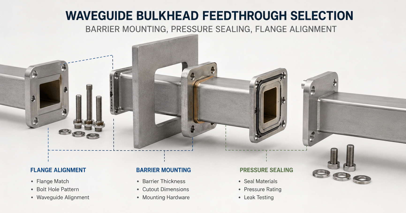
Where the system must maintain separate pressure zones, a properly selected waveguide pressure window can provide an environmental and pressure boundary while allowing RF energy to pass. The window’s waveguide size, frequency range, flange, pressure rating, insertion loss, VSWR and power capability must match the complete system.[5]
Before commissioning a waveguide pressure inlet, complete the following review:
- Confirm the final waveguide size and flange designation.
- Verify the fitting thread, tube size, valve type and gas-source connection.
- Check every component in the pressure boundary and identify the lowest rating.
- Confirm gasket material, groove dimensions and RF-contact requirements.
- Clean and dry the internal waveguide surfaces.
- Purge using the approved dry gas and documented purge procedure.
- Perform local leak detection and whole-system pressure-decay testing.
- Set and secure the regulator, alarms and relief device.
- Record pressure, temperature, humidity or dew point after stabilization.
- Measure the required RF baseline, including VSWR or return loss and insertion loss where applicable.
The most reliable waveguide pressure inlet is not necessarily the component with the highest catalog pressure rating or largest connection. It is the inlet that matches the exact waveguide interface, uses compatible seals and fittings, remains within the lowest pressure limit of the system, supplies enough dry gas for purging and leakage makeup, and prevents condensation under the actual environmental temperature cycle.
For a custom selection, provide Dolph Microwave with the waveguide size, frequency range, flange designation, gas type, operating pressure, maximum allowable pressure, inlet thread, tubing OD, required section length, material, temperature range, gauge requirement and leak-test criteria. This information allows the pressure inlet to be reviewed as part of the complete RF and environmental boundary rather than as a generic pneumatic fitting.
References
- Dolph Microwave — Waveguide Pressure Inlets Section
- Dolph Microwave — Waveguide Gasket and O-Ring
- ASME B1.20.3 — Dryseal Pipe Threads, Inch
- ASTM E515-11(2022) — Standard Practice for Leaks Using Bubble Emission Techniques
- Dolph Microwave — Waveguide Pressure Windows
- ASME — Pressure Relief Devices: Design, Sizing, Construction, Inspection and Maintenance
- CommScope — Maintaining Optimal Air Pressure for Broadcast Transmission Systems
- Parker — Fluorocarbon O-Ring Material and Gas Permeability Information
- Parker — Nitrile O-Ring Material Information
- Parker — EPDM O-Ring Material Information