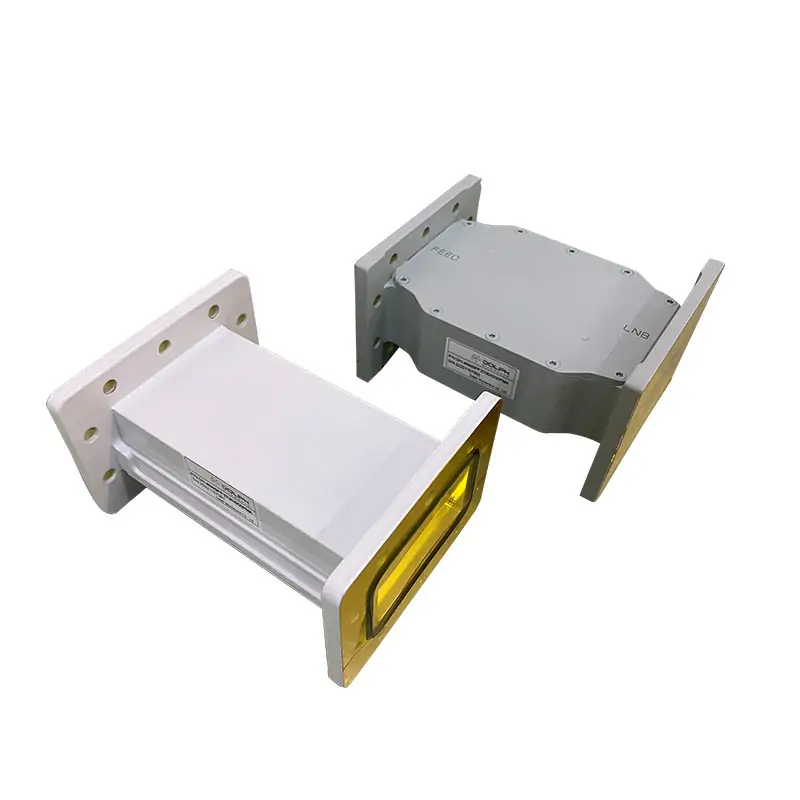
Filter construction and options
Filter functions
Listed examples: bandpass, lowpass and transmit-reject. The ordering key also includes highpass and receive-reject.
Interfaces and finish
Cover/grooved flanges, aluminum or copper, Iridite per MIL-C-5541 internal finish and anticorrosion black-painted body finish.
Configuration
Standard and requested configurations are described for satellite, radar, wireless, research and telecommunications systems. Specify rejection in dB at each required frequency.
Standards and approval references
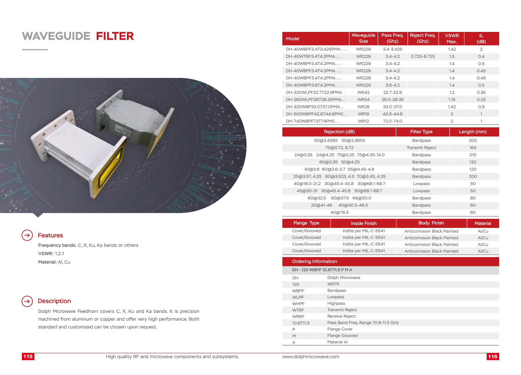
Download the original specification PDFSpecifications and configuration details
Filter model data
| Model | Waveguide Size | Pass Freq. (Ghz) | Reject Freq. (Ghz) | VSWR Max. | IL (dB) |
|---|---|---|---|---|---|
| DH-40WBPF3.4T3.425PMA…… | WR229 | 3.4-3.425 | 1.42 | 2 | |
| DH-40WTRF3.4T4.2PMA…… | WR229 | 3.4-4.2 | 5.725-6.725 | 1.5 | 0.4 |
| DH-40WBPF3.4T4.2PMA…… | WR229 | 3.4-4.2 | 1.4 | 0.5 | |
| DH-40WBPF3.4T4.2PMA…… | WR229 | 3.4-4.2 | 1.4 | 0.45 | |
| DH-40WBPF3.4T4.2PMA…… | WR229 | 3.4-4.2 | 1.4 | 0.45 | |
| DH-40WBPF3.6T4.2PMA…… | WR229 | 3.6-4.2 | 1.4 | 0.5 | |
| DH-220WLPF22.7T22.9PMA… | WR42 | 22.7-22.9 | 1.2 | 0.35 | |
| DH-260WLPF26T28.35PMA… | WR34 | 26.0-28.35 | 1.15 | 0.25 | |
| DH-320WBP33.0T37.0PMA… | WR28 | 33.0-37.0 | 1.42 | 0.9 | |
| DH-500WBPF42.6T44.6PMC… | WR19 | 42.6-44.6 | 2 | 1 | |
| DH-740WBPF72T74PMC… | WR12 | 72.0-74.0 | 2 | 1 |
Abbreviated model strings, repeated rows and empty cells are retained from the catalogue. Confirm the full part number; do not infer a value for a blank cell.
Rejection, function and length
| Rejection (dB) | Filter Type | Length (mm) |
|---|---|---|
| 50@3.4395 50@3.3855 | Bandpass | 200 |
| 70@5.72, 6.72 | Transmit Reject | 165 |
| 24@3.35 24@4.25 75@3.25 75@4.35-14.0 | Bandpass | 210 |
| 60@3.35 50@4.25 | Bandpass | 120 |
| 61@3.6 60@3.6-3.7 55@4.45-4.8 | Bandpass | 120 |
| 25@3.57, 4.25 60@3.525, 4.3 70@3.45, 4.35 | Bandpass | 200 |
| 40@18.0-21.2 30@45.4-45.8 30@68.1-68.7 | Lowpass | 50 |
| 45@30-31 30@45.4-45.8 30@68.1-68.7 | Lowpass | 50 |
| 60@32.5 60@37.5 66@50.0 | Bandpass | 80 |
| 20@41-46 40@40.5-46.5 | Bandpass | 60 |
| 40@76.5 | Bandpass | 60 |
Keep every rejection value with its printed frequency condition. The source rows are presented separately without merging model records.
Published finish entries
| Flange Type | Inside Finish | Body Finish | Material |
|---|---|---|---|
| Cover/Grooved | Iridite per MIL-C-5541 | Anticorrosion Black Painted | Al/Cu |
| Cover/Grooved | Iridite per MIL-C-5541 | Anticorrosion Black Painted | Al/Cu |
| Cover/Grooved | Iridite per MIL-C-5541 | Anticorrosion Black Painted | Al/Cu |
| Cover/Grooved | Iridite per MIL-C-5541 | Anticorrosion Black Painted | Al/Cu |
The source contains four repeated finish rows and eleven electrical rows. No extra row-to-model relationship has been inferred.
Ordering information: DH – 120 WBPF 10.8T11.5 P M A
| Code | Published meaning |
|---|---|
| DH | Dolph Microwave |
| 120 | WR75 |
| WBPF | Bandpass |
| WLPF | Lowpass |
| WHPF | Highpass |
| WTRF | Transmit Reject |
| WRRF | Receive Reject |
| 10.8T11.5 | Pass Band Freq. Range 10.8-11.5 GHz |
| P | Flange Cover |
| M | Flange Grooved |
| A | Material Al |
Product-family reference from the original page
The entries below are retained as published. Where they differ from the model-specific catalogue, confirm the selected configuration using the notes above.
| Specification | Details |
|---|---|
| Frequency Bands | C, X, Ku, Ka |
| VSWR | 1.2:1 |
| Material | Aluminum (Al), Copper (Cu) |
Drawings and original documents
Waveguide Filter
Download PDFView original pages (1)
FLANGE TYPE DESIGNATIONS INFORMATION
Download PDFOriginal flange designations and dimensional reference. Match the exact interface shown on your assembly drawing.
Related products
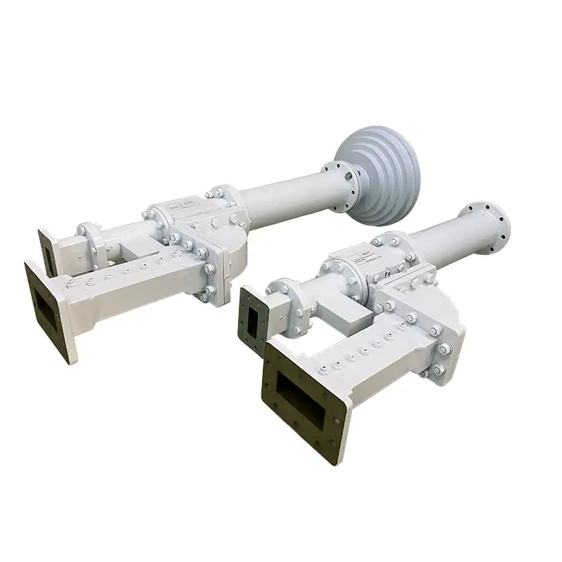
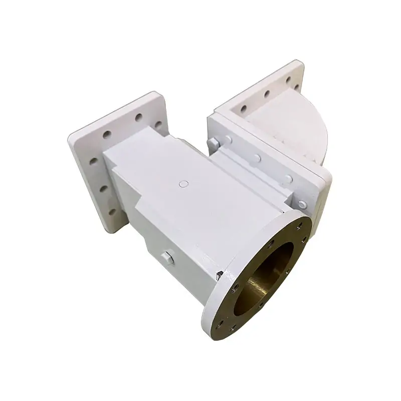
For a dedicated WR75 model, see WR75 Waveguide Bandpass Filter. A feed-network inquiry can also include the Waveguide Diplexer.

Include these details in your inquiry
- Passband start and stop frequencies
- Maximum insertion loss and VSWR
- Required rejection in dB at each frequency or range
- CW/peak power and operating conditions
- Waveguide size, flange codes and available length
- Material, finish and quantity