What We Match Before Quotation
Rx and Tx frequency ranges
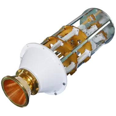
State the two bands separately. The published datasheet includes C-, X-, Ku-, DBS- and Ka-band configurations with different receive and transmit ranges.
Polarization and rejection
Published configurations include linear, circular and co-polarized arrangements. Tell us the required polarization, cross-polarization and rejection or isolation target.
Power and interfaces
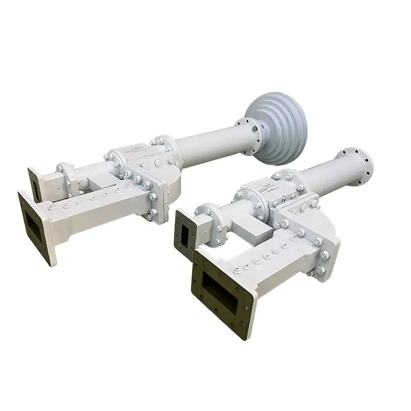
Include handling power, Tx/Rx interface, common-port interface and any flange requirement. The model sheet contains WR and SMA interface examples.
Mechanical layout
Send the mating drawing, available envelope or a simple sketch when the standard layout does not fit. Custom waveguide assemblies can be reviewed with the diplexer interfaces together.
Published Product Specifications
| Specification | Details |
|---|---|
| Frequency Bands | C, X, Ku, Ka, or others |
| VSWR | Excellent |
| Insertion Loss | Low |
| Isolation | High |
| Material | Aluminum (Al), Copper (Cu) |
| Structure | Compact |
| Customization | Available for specific needs |
Three-port RF path
The published diplexer structure uses separate receiving and transmitting ports with a common port connected to the antenna or antenna feed.
Model-specific values require confirmation
The published page confirms C, X, Ku and Ka-band options with low insertion loss, high isolation and aluminum or copper construction. Confirm numeric RF limits, polarization, interfaces and power against the selected datasheet and quotation.
Ordering code is defined in the sheet
Use the published ordering information together with your final frequency, polarization and interface requirement when requesting a quote.
Official Product Datasheet
Use the official PDF as an engineering reference and confirm the exact model, RF limits and interfaces in the quotation. The verified product-page specifications above remain the authoritative summary in this page body.
Use the Diplexer as Part of the Feed Chain
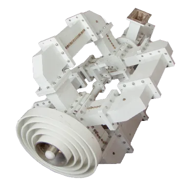
For antenna feed work, the diplexer can be reviewed together with the parts connected before and after it. This helps keep the band plan, polarization and interfaces consistent across the assembly.
From Drawing to Tested Hardware
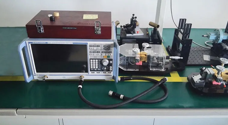
Manufacturing in-house
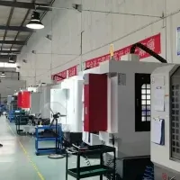
Dolph lists CNC machining, turning, waveguide forming and bending, anodising and passivation, abrasive machining, diamond grinding, electrolytic and electroless plating, soldering and brazing of Copper, Copper alloys and Aluminum, and electroforming.
Custom interface work
For non-standard layouts, Dolph can work from detailed drawings or simple sketches and review custom bends, waveguide sections and end flanges with the required RF interfaces.
Inspection requirement can be defined in the RFQ
If your procurement package needs specific RF limits, inspection evidence or test reports, include the required method, frequency points and acceptance limits before order release.
Published Test Resources
Supplier Information You Can Verify

Quality Documentation
Request current quality-system documentation for supplier qualification.
Founded in 2001
The company states that the former state-owned 806 Factory was its predecessor.

One-Year Warranty
Products are warranted against defective material and workmanship for one year from delivery, subject to Dolph Microwave warranty terms.

Compliance Process Capability
Request the applicable process-compliance documentation for the quoted configuration.