A waveguide quick disconnect should not be selected only because it can be opened without conventional flange bolts. A reliable assembly must perform three functions at the same time: match the existing waveguide interface, create consistent mechanical contact, and preserve the required RF and environmental performance after repeated connections.
The word “quick” describes the locking method, not the quality of the connection. An assembly that closes in seconds can still produce poor return loss, unstable insertion loss, RF leakage, or pressure leakage if the waveguide aperture, flange geometry, alignment features, sealing face, or contact force are incorrect.
Selection must therefore begin with the complete interface drawing rather than a general waveguide designation. “WR90,” “WR28,” or “WRD650” identifies a waveguide size or family, but it does not fully define the mating flange, hole pattern, seal groove, alignment arrangement, or locking mechanism.
| Selection Area | Information to Confirm | Evidence to Request |
|---|---|---|
| Waveguide interface | Waveguide size, aperture dimensions, flange family, flange designation | Dimensioned interface drawing |
| Mechanical fit | Hole positions, alignment pins, locking travel, available installation clearance | Assembly drawing and installation instructions |
| Sealing | Cover, grooved, choke, gasketed, pressure-rated, or non-pressure interface | Seal drawing, material data, pressure and leakage criteria |
| RF performance | Operating band, insertion loss, return loss or VSWR, power level | Full-band S-parameter test report |
| Repeated operation | Connection-cycle requirement, wear limits, inspection interval | Repeatability or endurance test results |
Dolph Microwave publishes double-ridged waveguide quick disconnect assemblies covering multiple WRD waveguide sizes, with model-dependent frequency ranges and flat or grooved flange configurations. These published configurations are a useful starting point, but the selected part must still be checked against the actual mating interface, installation environment, RF requirements, and sealing conditions.
Table of Contents
Flange Compatibility
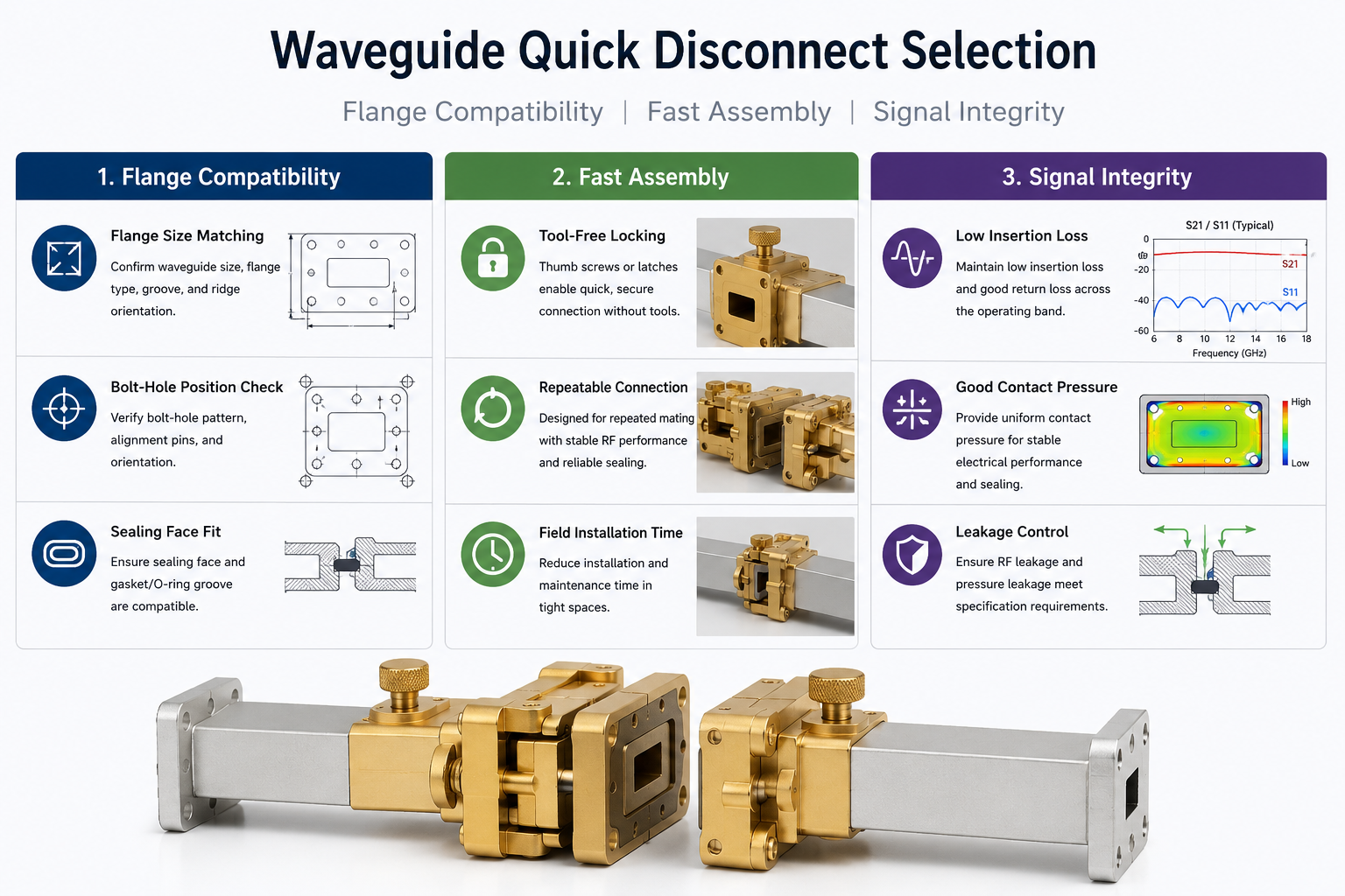
Flange compatibility is the first selection gate. A quick disconnect mechanism cannot correct an incompatible aperture, incorrect flange family, reversed ridge orientation, different bolt pattern, or unsuitable sealing surface. These conditions must be resolved before installation speed is considered.
Flange Size Matching
Start by confirming both the waveguide size and the complete flange designation. The waveguide size defines the nominal transmission path, while the flange designation defines the physical connection around that path.
For ordinary rectangular waveguides, IEC 60154-2:2016 specifies flange dimensions and mechanical requirements intended to support compatibility, practical interchangeability, and adequate electrical performance. Depending on the project, North American EIA, CPR, UG, military, or manufacturer-specific flange definitions may also apply.
Do not approve a quick disconnect based only on statements such as “compatible with WR90” or “suitable for X-band.” The following details should appear on the approved drawing:
- Internal waveguide aperture width and height
- Waveguide orientation and broad-wall direction
- Ridge dimensions and ridge orientation for double-ridged waveguide
- Flange outside dimensions and thickness
- Cover, grooved, choke, contact, or pressure flange type
- Gasket or O-ring groove dimensions, where applicable
- Alignment-hole and pin dimensions
- Locking surface, shoulder, or clamping-edge geometry
Ordinary rectangular waveguide and double-ridged waveguide interfaces must not be treated as interchangeable merely because their operating bands overlap. IEC 60154-2 primarily addresses ordinary rectangular waveguide flanges. A double-ridged quick disconnect normally requires the manufacturer’s controlled interface drawing because the ridge geometry and associated flange details are part of the RF boundary.
Dolph Microwave’s published quick disconnect range currently identifies models from WRD840 through WRD180, with corresponding flat and grooved flange part designations. Buyers should place the exact Dolph flange code and the mating equipment drawing in the purchase specification rather than relying on the WRD size alone.
Further reading: Waveguide Flange Standard EIA & IEC.
Bolt-Hole Position Check
Even when the waveguide aperture is correct, the interface may remain incompatible because of differences in bolt-hole count, center spacing, hole diameter, thread type, counterbore geometry, or alignment-pin location.
A quick disconnect may replace some or all conventional bolts with thumb screws, clamps, latches, or a retaining frame. However, the mating flange still needs sufficient geometric control to prevent lateral offset and angular misalignment. The locking device should pull the two faces together; it should not be used to force two incorrectly positioned apertures into alignment.
IEC 60154-2 notes that post-drilling alignment holes after the flange has been mounted can improve electrical performance. This matters because the alignment holes are referenced to the finished waveguide path rather than only to an unassembled flange blank.
Before approving the connection, inspect or measure:
- The center-to-center distance between all mounting or locating holes.
- The position of each hole relative to the waveguide aperture.
- The diameter and engagement length of alignment pins.
- Whether the mating holes are threaded, clearance, dowel, or combination holes.
- The rotational orientation of the aperture, ridge, seal groove, and locking features.
- The clearance needed to operate the latch or thumb screw after the waveguide is installed.
Misalignment risk becomes more critical as the waveguide dimensions become smaller and the operating frequency increases. NIST research on rectangular-waveguide calibration shows that imperfect interfaces between test ports, calibration standards, and devices under test can introduce inconsistencies into measured results. The same principle applies in service: the mechanical interface is part of the RF path, not an independent mounting detail.
If an existing system uses a military flange, verify the exact specification sheet rather than citing only the general specification. The U.S. Defense Logistics Agency maintains active MIL-DTL-3922 waveguide flange detail specifications, with individual sheets defining particular flange configurations.
Sealing Face Fit
The two flange faces must be compatible in both electrical-contact and sealing geometry. Matching external dimensions do not prove that the sealing faces are designed to work together.
Common configurations include:
- A flat cover flange against a compatible flat or contact flange
- A cover flange paired with a grooved flange containing a gasket or O-ring
- A choke flange paired with its specified mating face
- A pressure flange using a defined seal groove and compression limit
- A conductive gasket arrangement supporting both sealing and EMI continuity
Check the flange faces for flatness, burrs, dents, scratches, coating buildup, corrosion, particles, and damaged seal grooves. A locking mechanism cannot compensate for a raised burr or debris trapped between the mating surfaces. These defects can create local gaps, uneven contact pressure, seal damage, and unstable RF performance.
Seal material must be selected according to temperature, pressure, gas, humidity, outdoor exposure, compression set, outgassing, and required electrical conductivity. Dolph Microwave lists conductive silicone and ordinary silicone options within its waveguide gasket and O-ring range, but material approval should be based on the actual service environment rather than material name alone.
A flange described as “grooved” is not automatically pressure-tight. Pressure capability requires a defined seal, controlled compression, suitable flange stiffness, and a documented pressure and leakage test.
NASA sealing guidance emphasizes correct seal configuration, material selection, clean and inspected flange surfaces, controlled installation, and post-assembly leak testing. These principles are directly relevant when a waveguide quick disconnect also forms part of a pressurized or moisture-controlled waveguide run.
Fast Assembly
A quick disconnect is valuable when waveguide sections must be installed, removed, exchanged, cleaned, transported, or serviced frequently. However, installation speed should be measured only after compatibility, lock security, and RF performance have been demonstrated.
Tool-Free Locking
A tool-free mechanism may use thumb screws, over-center clamps, captive latches, retaining rings, or another manually operated locking system. The mechanism should create a positive and repeatable locked condition without requiring the operator to estimate the final contact pressure.
Dolph Microwave’s double-ridged quick disconnect assemblies use a thumb-screw clamping arrangement. When evaluating this or another mechanism, confirm:
- Whether the operator can see or feel that the connection is fully locked
- Whether the lock has a positive stop or defined end position
- Whether gloves can be used during field installation
- Whether nearby waveguide sections obstruct the locking motion
- Whether the mechanism can loosen under vibration or repeated handling
- Whether a secondary retention feature is required
- Whether the lock can be released accidentally by cable, clothing, or equipment contact
- Whether the locking force remains within specification across the operating temperature range
“Tool-free” should not be interpreted as “no inspection required.” The operator must still inspect the aperture, mating faces, alignment features, seal, and lock before energizing or pressurizing the system.
A well-designed mechanism should pull the flanges together in a controlled direction. If the operator must twist, lever, or force the waveguide to make the lock engage, the system may have an alignment, support, or flange-compatibility problem.
Repeatable Connection
The main advantage of a quick disconnect is lost if RF performance changes after each reconnection. Repeatability therefore needs to be treated as a measurable acceptance requirement rather than a subjective claim.
Connection repeatability can be affected by:
- Wear in the alignment pins or holes
- Latch, thread, or clamp wear
- Deformation of the flange or locking frame
- Gasket compression set
- Coating wear or corrosion on contact surfaces
- Contamination introduced during field handling
- Different locking force between operators
- Unsupported waveguide weight or external mechanical stress
The required number of connection cycles should be defined by the application. A laboratory fixture changed several times per day requires a different endurance plan from an emergency field section expected to be opened only during maintenance.
A practical repeatability qualification can include the following sequence:
- Record the initial full-band S11 and S21 results.
- Disconnect and reconnect the assembly using the approved procedure.
- Repeat the operation for the specified number of cycles.
- Record S-parameters at defined intervals.
- Inspect the flange faces, locating features, seals, and locking components.
- Compare the spread between repeated measurements with the project acceptance limits.
NIST studies of dimensional traceability and calibrated scattering parameters show why physical dimensions and connection interfaces must be included in the measurement uncertainty assessment. For a quick disconnect, this means the buyer should ask not only for a single “passed” RF plot but also for evidence that the interface remains stable after repeated assembly.
Seal replacement intervals should also be defined. An elastomeric gasket may continue to look serviceable while its compression recovery has changed. Where pressure retention is required, repeat RF measurements alone are insufficient; a leakage test must be included after the relevant connection cycles.
Field Installation Time
Field installation time should be measured using a defined procedure. Statements such as “connects in seconds” or “reduces installation time by 70%” are not meaningful unless the starting condition, comparison method, operator, access conditions, and completion criteria are stated.
A useful installation-time trial should specify:
- Whether the waveguide sections are already positioned and supported
- Whether protective covers must be removed and replaced
- Whether the mating faces require cleaning
- Whether a gasket must be installed or inspected
- Whether the operator is wearing field gloves
- Whether access is unrestricted or limited by surrounding equipment
- Whether visual inspection is included in the recorded time
- Whether RF verification or pressure testing is included
For procurement comparison, use the same trained operator and representative installation layout for each candidate. Conduct several connection and disconnection cycles rather than relying on the fastest single attempt. Record the median time, unsuccessful attempts, alignment corrections, and any tool use.
The installation should be considered complete only when the assembly is correctly aligned, fully locked, visually inspected, and ready for the required verification. A mechanism that closes quickly but needs repeated adjustment before passing the RF test is not a fast field solution.
Waveguide support must also be included in installation planning. The quick disconnect should not carry the unsupported weight of a long rigid waveguide run. External bending or torsional loads can tilt the mating faces, increase wear, and make subsequent connections less repeatable.
Signal Integrity
Signal integrity must be verified across the specified operating band and under the actual connection conditions. Visual fit and mechanical locking are not proof of acceptable microwave performance.
Low Insertion Loss
Insertion loss measures the reduction in transmitted signal power caused by adding the quick disconnect assembly to the RF path. It is normally expressed in decibels and evaluated through a two-port S21 or S12 measurement.
Return loss or VSWR evaluates reflection caused by impedance discontinuities. It does not directly measure total transmitted loss. A product can show an acceptable VSWR while still having additional conductive, geometric, or interface loss. Buyers should therefore request both:
- Insertion loss or transmission coefficient across the complete operating band
- Return loss or VSWR at both ports across the complete operating band
Keysight identifies S21 as the direct two-port measurement commonly used for insertion loss and distinguishes insertion loss from return loss. The two parameters describe related but different aspects of RF performance.
Dolph Microwave’s published quick disconnect table lists model-dependent VSWR values, typically 1.15:1 or 1.2:1 for the listed WRD configurations. These figures provide matching information, but the project specification should separately define the maximum acceptable insertion loss.
RF acceptance documentation should state:
- Test frequency range and frequency-point spacing
- Calibration method and calibration reference plane
- Waveguide adapters and test-port configuration
- Measured S11, S22, S21, and S12 where applicable
- Measurement uncertainty or guard band
- Connection condition and locking method
- Whether the result is from a prototype, qualification unit, or delivered production unit
Test-port quality matters. NIST has documented how imperfect interfaces between rectangular-waveguide test ports, calibration standards, and devices under test can introduce calibration inconsistencies. The test setup should therefore use compatible, clean, aligned, and properly supported ports rather than treating the flange connection as an insignificant fixture detail.
Good Contact Pressure
The locking mechanism must create enough contact pressure to seat the mating faces, maintain electrical continuity, and compress the specified seal. That pressure should also be sufficiently uniform to prevent one side of the flange from remaining open.
Insufficient pressure can cause:
- Microscopic or visible gaps at the joint
- Poor conductive continuity
- Higher reflection or unstable insertion loss
- RF leakage
- Pressure or moisture leakage
- Movement under vibration
Excessive pressure can also create problems, including flange deformation, crushed gaskets, damaged O-rings, worn threads, distorted locking components, and reduced connection life. More force is not automatically better.
There is no universal contact-force value for every waveguide quick disconnect. The required force depends on flange size, material, thickness, flatness, locking-point location, seal type, internal pressure, temperature, vibration, and allowable deformation.
The locking design should provide controlled engagement rather than relying on operator strength. Useful verification methods include:
- Checking the locked position against a mechanical stop or indicator.
- Measuring clamp force or locking torque during qualification.
- Using pressure-sensitive film during development to evaluate contact distribution.
- Inspecting seal compression against the approved groove design.
- Repeating S-parameter measurements with different trained operators.
- Testing after vibration, temperature cycling, or repeated connection where required.
Contact pressure should be considered together with flange support. A correctly designed quick disconnect can still produce uneven contact if the connected waveguide sections are pulling the joint sideways or if mounting brackets force the flanges out of parallel.
Leakage Control
“Leakage” must be defined in the purchase specification because it can refer to two different failure modes:
| Leakage Type | Main Concern | Typical Verification |
|---|---|---|
| RF leakage | Electromagnetic energy escaping through a flange gap or discontinuity | S-parameter testing and application-specific RF leakage or shielding measurements |
| Gas or pressure leakage | Pressurizing gas, dry air, nitrogen, or another controlled medium escaping through the joint | Pressure-decay, bubble, tracer-gas, helium, or another approved leak-test method |
RF leakage is primarily controlled by accurate aperture alignment, flat and clean conductive surfaces, suitable contact pressure, and a flange design appropriate for the operating frequency and power. A conductive gasket may support EMI continuity, but it does not correct a fundamentally misaligned waveguide interface.
For pressure-controlled waveguide runs, the quick disconnect must have a documented maximum operating pressure, proof or test pressure where required, compatible seal material, allowable leakage rate, and stated test method. Do not assume pressure capability because an O-ring is visible in the assembly.
ISO 20485:2017 describes tracer-gas techniques used for leak detection. When a tracer-gas or helium test is specified, the procedure should identify the test pressure, tracer gas, detector, calibration arrangement, stabilization time, background level, acceptance limit, and test temperature.
Before a leakage test, inspect and clean the flange and seal according to the approved procedure. Dirt, fibers, metal particles, scratches, twisted seals, and incorrectly seated gaskets can all create leakage paths. NASA guidance identifies careful joint design, seal selection, surface cleaning, inspection, controlled assembly, and leak testing as key practices for low-leakage flange systems.
Where the waveguide is both pressurized and used at significant RF power, the qualification plan should evaluate the complete operating condition rather than testing pressure and RF performance as unrelated functions. Temperature rise, pressure load, seal behavior, flange deformation, and connection force can interact.
A complete waveguide quick disconnect specification should therefore include the following acceptance information:
- Exact waveguide and flange designation
- Approved interface drawing and orientation
- Locking mechanism and locked-position criteria
- Operating frequency range and power conditions
- Maximum insertion loss across the band
- Minimum return loss or maximum VSWR across the band
- Required connection-cycle life and RF repeatability
- Operating temperature and environmental conditions
- Seal type, material, and replacement requirements
- Maximum operating pressure and allowable leakage rate, if applicable
- Required RF, mechanical, pressure, and environmental test reports
The correct waveguide quick disconnect is not simply the model with the fastest latch. It is the model that mates with the exact flange, locks predictably, remains repeatable after reconnection, and meets separate RF and leakage acceptance limits.
For a standard or double-ridged interface, provide Dolph Microwave with the mating flange drawing, waveguide size, operating frequency, power level, installation-clearance limits, environmental conditions, connection-cycle requirement, and pressure or leakage criteria. This information allows the locking mechanism, flange geometry, material, finish, seal, and test plan to be reviewed as one complete interface.
Related Dolph Microwave resources:
- Double-Ridged Waveguide Quick Disconnect Assembly
- Waveguide Flange Standard EIA & IEC
- Waveguide Gasket and O-Ring
- Waveguide Accessories
- Custom Microwave Products
- Contact Dolph Microwave
References
- International Electrotechnical Commission. IEC 60154-2:2016—Flanges for Waveguides, Part 2: Ordinary Rectangular Waveguides.
- Defense Logistics Agency ASSIST. MIL-DTL-3922 Waveguide Flange Detail Specification.
- Williams, D. F., National Institute of Standards and Technology. Rectangular-Waveguide Vector-Network-Analyzer Calibrations With Imperfect Test Ports.
- Jargon, J. A. et al., National Institute of Standards and Technology. Physical Models and Dimensional Traceability of WR15 Rectangular Waveguide Standards.
- Keysight Technologies. Two-Port vs. One-Port Insertion Loss Measurements.
- International Organization for Standardization. ISO 20485:2017—Non-destructive Testing, Leak Testing, Tracer Gas Method.
- NASA Lessons Learned Information System. Design and Test Practices for Low-Leakage Seals and Flange Joints.
- Dolph Microwave. Quick Disconnect Assembly Product Information.