
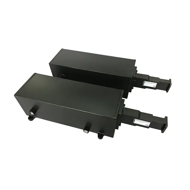
High-Power Water-Cooled Waveguide Loads
Published WR975–WR28 models cover individual bands between 0.76 and 40 GHz, with model-specific CW ratings from 0.5 to 150 kW. Confirm frequency, power, duty cycle, flange and cooling conditions for model selection.
Product Construction
Send the operating data and we can check the WWHPL model
Frequency range, WR size, CW power, peak power and duty cycle, flange, cooling connection, inlet water temperature, mechanical envelope and quantity.
RF data
Mechanical interface
Cooling connection
Complete Model Specifications
Use the exact model row for frequency, waveguide size, CW power, cooling, water temperature, tubing and flange selection.
| MODEL | FREQUENCY RANGE (GHz) | WG SIZE | VSWR Max. | POWER RATING CW (KW) | COOLING METHOD | INLET WATER TEMP | OUTPUT WATER TEMP | WATER VALVES CONNECTOR | WATER TUBING O.D. (mm) | FLANGES TYPE | MATERIAL | DATASHEET | COVER |
|---|---|---|---|---|---|---|---|---|---|---|---|---|---|
| DH-9WWHPL… | 0.76-1.15 | WR975 | 1.2:1 | 50~150 | Water Cooled | 15°C to 40°C | 85°C | Push-In Fitting QS | 10, 12, 16 | UDR9 | Al | STEP | |
| DH-12WWHPL… | 0.96-1.46 | WR770 | 1.2:1 | 50~150 | Water Cooled | 15°C to 40°C | 85°C | Push-In Fitting QS | 10, 12, 16 | UDR12 | Al | STEP | |
| DH-14WWHPL… | 1.13-1.73 | WR650 | 1.2:1 | 50~150 | Water Cooled | 15°C to 40°C | 85°C | Push-In Fitting QS | 10, 12, 16 | UDR14 | Al | STEP | |
| DH-22WWHPL… | 1.72-2.61 | WR430 | 1.2:1 | 10~60 | Water Cooled | 15°C to 40°C | 85°C | Push-In Fitting QS | 10, 12, 16 | UDR22 | Al | STEP | |
| DH-26WWHPL… | 2.17-3.3 | WR340 | 1.2:1 | 10~50 | Water Cooled | 15°C to 40°C | 85°C | Push-In Fitting QS | 10, 12, 16 | UDR26 | Al | STEP | |
| DH-32WWHPL… | 2.6-3.95 | WR284 | 1.2:1 | 3~12 | Water Cooled | 15°C to 40°C | 85°C | Push-In Fitting QS | 10, 12, 16 | UDR32 | Al | STEP | |
| DH-40WWHPL… | 3.22-4.9 | WR229 | 1.2:1 | 3~12 | Water Cooled | 15°C to 40°C | 85°C | Push-In Fitting QS | 10, 12, 16 | UDR40 | Al | STEP | |
| DH-48WWHPL… | 3.94-5.99 | WR187 | 1.2:1 | 3~12 | Water Cooled | 15°C to 40°C | 85°C | Push-In Fitting QS | 10, 12, 16 | UDR48 | Al | STEP | |
| DH-58WWHPL… | 4.64-7.05 | WR159 | 1.2:1 | 3~10 | Water Cooled | 15°C to 40°C | 85°C | Push-In Fitting QS | 10, 12, 16 | UDR58 | Al | STEP | |
| DH-70WWHPL… | 5.38-8.17 | WR137 | 1.2:1 | 1~10 | Water Cooled | 15°C to 40°C | 85°C | Push-In Fitting QS | 10, 12, 16 | UDR70 | Al | STEP | |
| DH-84WWHPL… | 6.57-9.99 | WR112 | 1.2:1 | 1~10 | Water Cooled | 15°C to 40°C | 85°C | Push-In Fitting QS | 10, 12, 16 | UDR84/UBR84 | Al | STEP | |
| DH-100WWHPL… | 8.2-12.5 | WR90 | 1.2:1 | 1~10 | Water Cooled | 15°C to 40°C | 85°C | Push-In Fitting QS | 10, 12, 16 | UDR100/UBR100 | Al | STEP | |
| DH-120WWHPL… | 9.84-15 | WR75 | 1.2:1 | 1~10 | Water Cooled | 15°C to 40°C | 85°C | Push-In Fitting QS | 10, 12, 16 | UBR120 | Al | STEP | |
| DH-140WWHPL… | 11.9-18 | WR62 | 1.2:1 | 0.5-5 | Water Cooled | 15°C to 40°C | 85°C | Push-In Fitting QS | 10, 12, 16 | UBR140 | Al | STEP | |
| DH-180WWHPL… | 14.5-22 | WR51 | 1.2:1 | 0.5-5 | Water Cooled | 15°C to 40°C | 85°C | Push-In Fitting QS | 10, 12, 16 | UBR180 | Al | STEP | |
| DH-220WWHPL… | 17.6-26.7 | WR42 | 1.2:1 | 0.5-5 | Water Cooled | 15°C to 40°C | 85°C | Push-In Fitting QS | 10, 12, 16 | UBR220 | Al | STEP | |
| DH-260WWHPL… | 21.7-33 | WR34 | 1.2:1 | 0.5-5 | Water Cooled | 15°C to 40°C | 85°C | Push-In Fitting QS | 10, 12, 16 | UBR260 | Al | STEP | |
| DH-320WWHPL… | 26.3-40 | WR28 | 1.2:1 | 0.5-5 | Water Cooled | 15°C to 40°C | 85°C | Push-In Fitting QS | 10, 12, 16 | UBR320 | Al | STEP |
Not sure whether you need water cooling?
For lower average-power requirements, compare the air-cooled High Power Termination. For the full termination family, review Waveguide Termination.
Part Number Guide
Finish and Configuration Note
All Dolph-MW models include an surtec/corrosion protection treatment and are painted flat black. Flanges are unplated, polished and surtec. Other finishes and paint colors are available upon request.
The product description states identifies ultra-high temperature refractory ceramic absorbers, welded aluminium housings, internal water circulation and an integrated fine matcher.

Related High-Power Waveguide Components
Use when the high-power line must transition between waveguide and coaxial interfaces.
Use where alignment or routing requires a flexible waveguide section.
Check flange families and designation conventions before release.
Use when the required interface, size or system layout is outside the published model range.
Manufacturing, Test and Supplier Information
Need a custom high-power waveguide path around the load?
Send the load conditions together with the surrounding waveguide interfaces or drawing. Dolph also publishes custom waveguide assembly and high-power component manufacturing services.
Where the WWHPL Range Is Used
Published application areas include high-power RF system protection, research and high-energy physics equipment, industrial microwave systems, and test setups for amplifiers, transmitters and microwave sources.
For industrial systems centered on 915 MHz or 2450 MHz, see Dolph’s industrial microwave component capability. For a published high-power termination build, see the WR159 high-power termination report.







