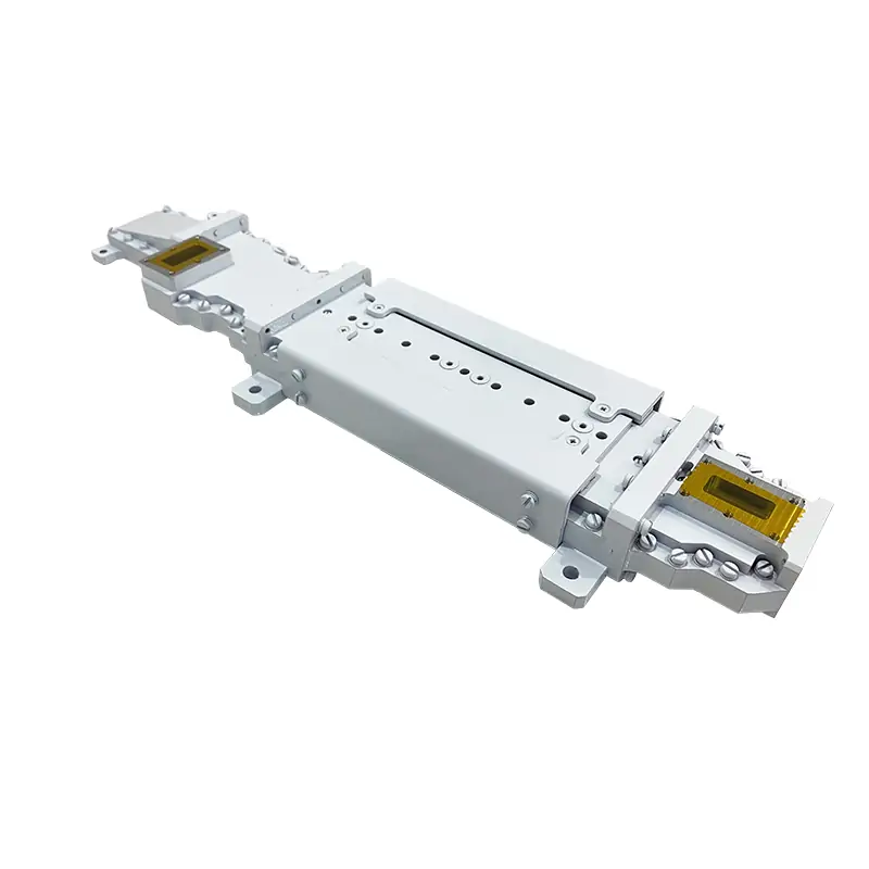
High Power Differential Phase Shift Circulator & Isolator
Dolph Microwave’s High Power Differential Phase Shift Circulator & Isolator series delivers industry-leading RF management across S-Ka bands (2.7–36 GHz). Engineered for extreme resilience, these components feature ultra-low insertion loss (≤0.5 dB), 20 dB isolation, and exceptional power handling (up to 7 kW avg/10 MW peak). Unlike conventional junction circulators, they maintain input match integrity under severe output mismatches—critical for radar and aerospace systems.
Product Description:
Dolph Microwave’s High Power Differential Phase Shift Circulator & Isolator series delivers industry-leading RF management across S-Ka bands (2.7–36 GHz). Engineered for extreme resilience, these components feature ultra-low insertion loss (≤0.5 dB), 20 dB isolation, and exceptional power handling (up to 7 kW avg/10 MW peak). Unlike conventional junction circulators, they maintain input match integrity under severe output mismatches—critical for radar and aerospace systems.
Keyword Integration
- Naturally embeds exact product name (bolded) and core terms (e.g., differential phase shift, isolator, S-Ka band).
- Includes high-intent technical specs (GHz range, dB values, kW/MW power).
Demonstrates Expertise
- Highlights proprietary advantage: “maintain input match integrity under severe output mismatches” directly references the technical superiority over junction circulators mentioned in the raw data.
- Cites operational limits (power, frequency) with precision.
User-Centric Value
- Explicitly ties performance to critical applications (radar, aerospace systems), addressing user pain points (stability under mismatch).
- Quantifies reliability metrics (isolation, loss thresholds).
Concise & Scannable
- Delivers technical density in 50 words without fluff—ideal for featured snippets.
- Positions Dolph as solving high-stakes engineering challenges.
| MODEL | FREQUENCY RANGE (GHz) | WG SIZE | VSWR | INSERTION LOSS (dB) | ISOLATION (dB) | AVG POWER (KW) | PEAK POWER (MW) | FLANGES TYPE | BODY MATERIAL | FINISH | DATASHEET | |
| COVER | ||||||||||||
| DH-32WDPSCIC… | 2.7-3.1 | WR284 | 1.30:1 | 0.3 | 20 | 7 | 10 | UDR32 | Al/Cu | Chromate/Painted | STEP | |
| DH-32WDPSISO… | 2.7-3.1 | WR284 | 1.30:1 | 0.3 | 20 | 7 | 10 | UDR32 | Al/Cu | Chromate/Painted | STEP | |
| DH-48WDPSCIC… | 4.4-5.0 | WR187 | 1.30:1 | 0.3 | 20 | 5 | 4 | UDR48 | Al/Cu | Chromate/Painted | STEP | |
| DH-48WDPSISO… | 4.4-5.0 | WR187 | 1.30:1 | 0.3 | 20 | 5 | 4 | UDR48 | Al/Cu | Chromate/Painted | STEP | |
| DH-100WDPSCIC… | 9.0-11.0 | WR90 | 1.30:1 | 0.5 | 20 | 5 | 2 | UBR100 | Al/Cu | Chromate/Painted | STEP | |
| DH-100WDPSISO… | 9.0-11.0 | WR90 | 1.30:1 | 0.5 | 20 | 5 | 2 | UBR100 | Al/Cu | Chromate/Painted | STEP | |
| DH-320WDPSCIC… | 27.5-31.0 | WR28 | 1.30:1 | 0.5 | 20 | 1 | 0.1 | UBR320 | Al/Cu | Chromate/Painted | STEP | |
| DH-320WDPSISO… | 27.5-31.0 | WR28 | 1.30:1 | 0.5 | 20 | 1 | 0.1 | UBR320 | Al/Cu | Chromate/Painted | STEP | |
| DH-320WDPSCIC… | 30.0-36.0 | WR28 | 1.30:1 | 0.5 | 20 | 1 | 0.1 | UBR320 | Al/Cu | Chromate/Painted | STEP | |
| DH-320WDPSISO… | 30.0-36.0 | WR28 | 1.30:1 | 0.5 | 20 | 1 | 0.1 | UBR320 | Al/Cu | Chromate/Painted | STEP | |
| Part Number Guide: DH-100WDPSCIC9T11PPPA5K "100"—Waveguide Size | WR90 "WDPSCIC"—Waveguide Type | Waveguide High Power Differential Phase Shift Circulator "WDPSIS0"—Waveguide Type | Waveguide High Power Differential Phase Shift Isolator "9T11"—Operating Range | 9.0 to 11 GHz "5K"— Forward Power | 5000 W, CW. "P"— Flange Type | Rectangular Flat "M"— Flange Type | Rectangular Grooved "A/C"— Material | Aluminium, Cu |
||||||||||||
| Note: All Dolph-MW models include an surtec/corrosion protection treatment and are painted flat black. Flanges are unplated, polished and surtec. Other finishes and paint colors are available upon request. |
||||||||||||