
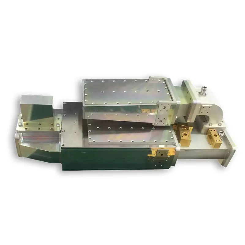
Waveguide Isolator Range at a Glance
Choose from standard, slim-type and high-power waveguide isolators. Final electrical limits, waveguide size, flange, material and dimensions follow the selected model or approved custom drawing.
The current standard model sheet below covers WR137 to WR10 and 5.38 to 112 GHz. Use the selected model row as the release value.
Standard Waveguide Isolator Models
The table keeps the published model data without merging values. Send the operating band and mating flange pair if you want Dolph Microwave to match the model before quotation.
| Model No. | Freq. Range (GHz) | Operating BW (MHz) | VSWR Max. | IL Max. (dB) | Isolation Min. (dB) | IEC WG | EIA WG | Flange | Material |
|---|---|---|---|---|---|---|---|---|---|
| DH-70WISO | 5.38-8.17 | 700 | 1.20 | 0.3 | 20 | R70 | WR137 | FDP/FDM | Al/Cu |
| DH-84WISO | 6.57-9.99 | 700 | 1.20 | 0.3 | 20 | R84 | WR112 | FBP/FBM/FBE | Al/Cu |
| DH-100WISO | 8.2-12.5 | 800 | 1.20 | 0.3 | 20 | R100 | WR90 | FBP/FBM/FBE | Al/Cu |
| DH-120WISO | 9.84-15.0 | 1000 | 1.20 | 0.3 | 20 | R120 | WR75 | FBP/FBM/FBE | Al/Cu |
| DH-140WISO | 11.9-18.0 | 1000 | 1.20 | 0.3 | 20 | R140 | WR62 | FBP/FBM/FBE | Al/Cu |
| DH-180WISO | 14.5-22.0 | 1000 | 1.20 | 0.3 | 20 | R180 | WR51 | FBP/FBM/FBE | Al/Cu |
| DH-220WISO | 17.6-26.7 | 2000 | 1.20 | 0.3 | 20 | R220 | WR42 | FBP/FBM/FBE | Al/Cu |
| DH-260WISO | 21.7-33.0 | 2000 | 1.20 | 0.3 | 20 | R260 | WR34 | FBP/FBM/FBE | Al/Cu |
| DH-320WISO | 26.3-40.0 | 2000 | 1.20 | 0.3 | 20 | R320 | WR28 | FBP/FBM/FBE | Al/Cu |
| DH-400WISO | 32.9-60.1 | 2000 | 1.30 | 0.6 | 20 | R400 | WR22 | FUGP | Cu |
| DH-500WISO | 39.2-59.6 | 2000 | 1.30 | 0.6 | 20 | R500 | WR19 | FUGP | Cu |
| DH-620WISO | 49.8-75.8 | 2000 | 1.30 | 0.6 | 20 | R620 | WR15 | FUGP | Cu |
| DH-740WISO | 60.5-91.9 | 2000 | 1.30 | 0.8 | 20 | R740 | WR12 | FUGP | Cu |
| DH-900WISO | 73.8-112 | 2000 | 1.30 | 1.0 | 20 | R900 | WR10 | FUGP | Cu |
Need a model check before you quote?
Send frequency range, waveguide size, forward power, reflected power, flange pair, size limit and quantity. We can check a standard model or review a custom build.
General, Slim-Type and High-Power Options
Use the product type that matches the space and power limits of your waveguide path. The published data stays separate so values from different constructions are not mixed.
General Isolator
Published general models cover multiple bands and custom dimensions. The wider the required bandwidth and the higher the reflected power, the more space may be needed for the transmission section and absorber.
Slim-Type Isolator
For installations with tight mechanical space. Published slim models list BJ100 to BJ320 waveguide types with model-specific loss, reverse loss, VSWR, reference power and size.
High-Power Differential Phase-Shift Isolator
For higher-power waveguide paths. Use the published high-power band table and model data below, then confirm the final operating limits in the quotation.
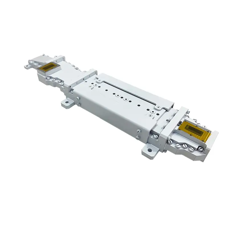
General Isolator Published Data
Typical values and product-model values are shown separately. Reference power and size are kept exactly as published in the product sheet.
| Freq. Band | Bandwidth | Forward Loss (dB) | Reverse Loss (dB) | VSWR | Ave. Power |
|---|---|---|---|---|---|
| L | 5% | 0.20 | 23 | 1.15 | 2KW |
| L | 10% | 0.25 | 21 | 1.17 | 2KW |
| L | 20% | 0.30 | 20 | 1.20 | 2KW |
| S | 5% | 0.20 | 23 | 1.15 | 1KW |
| S | 10% | 0.25 | 21 | 1.17 | 1KW |
| S | 20% | 0.30 | 20 | 1.20 | 1KW |
| C | 5% | 0.20 | 23 | 1.15 | 500W |
| C | 10% | 0.25 | 21 | 1.17 | 500W |
| C | 20% | 0.30 | 20 | 1.20 | 500W |
| X | 10% | 0.20 | 23 | 1.15 | 300W |
| X | 20% | 0.25 | 20 | 1.20 | 300W |
| Ku | 10% | 0.20 | 23 | 1.15 | 120W |
| Ku | 20% | 0.25 | 20 | 1.20 | 120W |
| K | 10% | 0.20 | 23 | 1.15 | 100W |
| K | 20% | 0.25 | 20 | 1.20 | 100W |
| Ka | 5% | 0.25 | 23 | 1.15 | 50W |
| Ka | 10% | 0.30 | 20 | 1.20 | 50W |
| V | 10% | 0.60 | 17 | 1.35 | 2W |
| U | 5% | 0.60 | 17 | 1.35 | 2W |
| E | 5% | 0.60 | 17 | 1.35 | 2W |
Full general isolator model data
| Model No. | Freq. Range (GHz) | WG Type | Forward Loss (dB) | Reverse Loss (dB) | VSWR | Ref. Power | Size |
|---|---|---|---|---|---|---|---|
| DH-GBG9029 | 2.01-2.13 | BJ22 | 0.50 | 20 | 1.5 | 1200W | 220*417*106.4 |
| DH-GBG9052 | 3.4-4.2 | BJ40 | 0.25 | 20 | 1.2 | 2000W | 265*138*69.85 |
| DH-GBG9051 | 5.49-5.51 | BJ48 | 0.30 | 25 | 1.12 | 2MW/2KW | 300*210*89.9 |
| DH-GBZ9011 | 5.8-6.4 | BJ70 | 0.20 | 20 | 1.25 | 1200W | 172.6*82.6*49.2 |
| DH-GBP9049 | 13-14 | BJ140 | 0.30 | 20 | 1.15 | 30W | 20*34.5*33 |
| DH-GBP9106 | 13-14.1 | BJ120 | 0.30 | 20 | 1.2 | 100W | 39*57.5*38.3 |
| DH-GBZ9019 | 13.75-14.5 | BJ120 | 0.20 | 23 | 1.15 | 300W | 38*90*38 |
| DH-GBP9085 | 14-16 | BJ140 | 0.25 | 18 | 1.3 | 10W | 45.72*22.86*19.05 |
| DH-GBP9105 | 14.6-15.3 | BJ120 | 0.30 | 20 | 1.2 | 100W | 39*57.5*38.3 |
| DH-GBP9039 | 15-18 | BJ180 | 0.40 | 20 | 1.2 | 20W | 38*86*33.3 |
| DH-GBP9076 | 16.3-17.3 | BJ220 | 0.40 | 18 | 1.3 | 50W | 23*40*15 |
| DH-GBG9009 | 16.5-17.5 | BJ140 | 0.30 | 24 | 1.15 | 1500W | 33*68*33 |
| DH-GBP9078 | 18.5-21.6 | BJ220 | 0.30 | 20 | 1.22 | 50W | 38*22.4*18 |
| DH-GBG9047A | 18.8-21.2 | BJ180 | 0.20 | 20 | 1.2 | 80W | 30*70*23.37 |
| DH-GBP9100 | 22.4-26.3 | BJ260 | 0.30 | 18 | 1.3 | 30W | 24*36*21.1 |
| DH-GBG9048 | 22.55-23.55 | BJ220 | 0.20 | 20 | 1.2 | 80W | 30*70*22.4 |
| DH-GBP9079 | 24.7-27.7 | BJ260 | 0.25 | 21 | 1.2 | 50W | 18*35*21.1 |
| DH-GBP9102 | 26.5-28.5 | BJ320 | 0.25 | 20 | 1.2 | 30W | 20*23*19 |
| DH-GBG9042 | 27.5-31 | BJ320 | 0.25 | 20 | 1.2 | 50W | 25*40*19.1 |
| DH-GBG9039 | 29.4-31 | BJ320 | 0.20 | 20 | 1.2 | 80W | 21*45*19.1 |
| DH-GBP9118 | 33-37 | BJ320 | 0.30 | 20 | 1.2 | 20W | 25*27*19.1 |
| DH-GBH9009 | 43-46 | BJ400 | 0.40 | 20 | 1.25 | 50W | 30*44*30 |
| DH-GBP9028 | 49-51 | BJ500 | 0.30 | 20 | 1.2 | 10W | 18*25*19.8 |
| DH-GBH9014 | 50-57.38 | BJ500 | 0.50 | 18 | 1.3 | 2W | 15*25.5*20 |
| DH-GBH9016 | 51-59 | BJ620 | 0.60 | 20 | 1.3 | 2W | 15*25.5*20 |
| DH-GBH9007 | 74-76 | BJ740 | 0.60 | 20 | 1.3 | 2W | 15*25*20 |
| DH-GBH9013 | 81-84 | BJ740 | 0.60 | 18 | 1.35 | 2W | 15*25.5*20 |
| DH-GBH9018 | 83.2-86.2 | BJ740 | 0.60 | 18 | 1.3 | 2W | 15*25.6*19 |
| DH-GBH9017 | 87-91 | BJ900 | 0.70 | 18 | 1.35 | 2W | 15*20.5*19.1 |
| DH-GBH9006 | 93.9-94.1 | BJ900 | 0.45 | 23 | 1.25 | 2W | 15*25*21 |
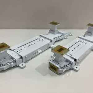
Slim-Type Waveguide Isolator Models
Use slim-type models when the isolator has to fit a smaller mechanical envelope. Do not select by waveguide type alone; check the full frequency range, loss, isolation, VSWR, reference power and size.
Published slim-type model data
| Model No. | Freq. Range (GHz) | WG Type | Forward Loss (dB) | Reverse Loss (dB) | VSWR | Ref. Power | Size |
|---|---|---|---|---|---|---|---|
| DH-GBP9075 | 9.1-9.9 | BJ100 | 0.30 | 20 | 1.3 | 30W | 16.2*41.4*60 |
| DH-GBP9061 | 12.2-12.8 | BJ120 | 0.50 | 18 | 1.3 | 10W | 12.7*44.5*38 |
| DH-GBP9071 | 12.55-13.05 | BJ140 | 0.30 | 20 | 1.15 | 30W | 12.7*50*27.5 |
| DH-WM-130-IS | 12.7-13.25 | BJ140 | 0.30 | 23 | 1.20 | 30W | 12.7*50*27.5 |
| DH-WM-187-IS | 17.7-19.7 | BJ220 | 0.40 | 19 | 1.30 | 20W | 9.53*31.75*22.4 |
| DH-WM-224-IS | 21.2-23.6 | BJ220 | 0.4 | 19 | 1.30 | 20W | 9.53*31.75*22.4 |
| DH-GBP9097 | 22-24 | BJ260 | 0.25 | 20 | 1.2 | 20W | 12*35*21.1 |
| DH-GBP9099 | 25.5-26.1 | BJ260 | 0.25 | 20 | 1.20 | 30W | 12*35*21.1 |
| DH-WM-282-IS | 27-29.5 | BJ320 | 0.30 | 18 | 1.30 | 20W | 9.35*31.75*19.5 |
| DH-GBP9080 | 27.5-31 | BJ320 | 0.30 | 20 | 1.25 | 20W | 9.35*31.75*19 |
| DH-GBP9113 | 28.1-30 | BJ260 | 0.25 | 20 | 1.20 | 5W | 12.7*32.1*21.1 |
| DH-GBP9065 | 29.4-31 | BJ320 | 0.30 | 20 | 1.20 | 20W | 8*31.8*19.1 |
| DH-GBP9082 | 30.5-31.5 | BJ320 | 0.30 | 20 | 1.25 | 20W | 9.5*30*19.3 |
| DH-WM-322-IS | 31-33.4 | BJ320 | 0.30 | 18 | 1.30 | 20W | 9.53*31.75*19.5 |
| DH-GBP9090 | 33-37 | BJ320 | 0.40 | 18 | 1.35 | 20W | 10*19.5*34.2 |
| DH-GBP9086 | 37-40.5 | BJ320 | 0.35 | 18 | 1.30 | 20W | 9.53*31.75*19.5 |
High-Power Differential Phase-Shift Isolator Data
The published PDF lists typical band values and five product models. For current dedicated differential phase-shift products, also review the high-power circulator and isolator range.
| Freq. Band | Bandwidth | Forward Loss (dB) | Reverse Loss (dB) | VSWR | Ave. Power |
|---|---|---|---|---|---|
| S | 20% | 0.40 | 20 | 1.2 | 40KW-CW |
| C | 20% | 0.40 | 20 | 1.2 | 10KW-CW |
| X | 20% | 0.40 | 20 | 1.2 | 1.5KW-CW |
| Ku | 20% | 0.40 | 20 | 1.2 | 1KW-CW |
| K | 20% | 0.45 | 20 | 1.2 | 800W-CW |
| Ka | 15% | 0.45 | 20 | 1.2 | 500W-CW |
| V | 10% | 0.45 | 20 | 1.2 | 300W-CW |
| Model No. | Freq. Range (GHz) | WG Type | Forward Loss (dB) | Reverse Loss (dB) | VSWR | Ref. Power | Size |
|---|---|---|---|---|---|---|---|
| DH-GBC9004 | 2.75-3.05 | BJ32 | 0.40 | 23 | 1.15 | 5KW/140KW | 640*376.8*257.5 |
| DH-GBC9009 | 3.3-3.6 | BJ32 | 0.25 | 20 | 1.15 | 10KW | 660*398*300 |
| DH-GBC9065 | 5.8-6.5 | BJ70 | 0.25 | 20 | 1.2 | 3500W | 437.2*128*121 |
| DH-GBC9010 | 12.25-12.75 | BJ120 | 0.30 | 25 | 1.15 | 1.5KW | 199*70*60 |
| DH-GBC9001 | 23.5-25.5 | BJ260 | 0.35 | 25 | 1.20 | 1KW | 167*68*77 |
Send the Inputs That Control the Build
A useful quotation needs the actual RF and mechanical limits. Send these values together so the model, absorber size, flange and body dimensions can be checked at the same time.
Check the Flange Before Order Release
Waveguide size alone does not define the mating interface. Confirm the cover or grooved flange at both ends and match the exact EIA or IEC designation used by the connected equipment.
Use the Waveguide Flange Standard EIA & IEC for designation matching. For bolt patterns, gasket fit and common mix-ups, see the Waveguide Flange Size Guide.
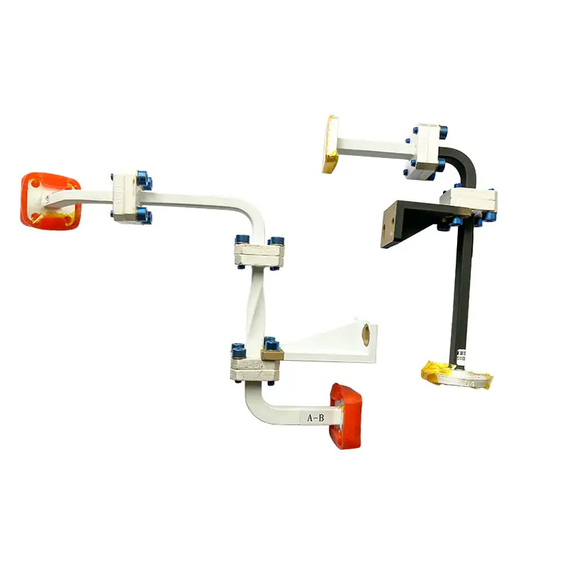
Made and Tested in Dolph Microwave’s Xi’an Factory
CNC machining, turning, waveguide forming and bending, soldering, brazing, plating, electroforming and final RF testing are listed as in-house capabilities. The company states ISO 9001:2015 certification and a one-year warranty from delivery for defective material and workmanship.
In-House Manufacturing
Machining, forming, brazing, plating and related microwave-component processes are handled in the Xi’an workshop.
RF Test Facilities
The manufacturing information lists a testing laboratory and microwave chamber for electrical checks before shipment.
Supplier Qualification
ISO 9001:2015 certification and the published one-year warranty can be reviewed as part of your supplier approval process.
Related Parts for the Same Waveguide Path
Use the isolator as one part of the full RF path. The related component depends on what the next section of the system needs to do.
Ready for a model and drawing review?
Send the band, power, waveguide size, flange pair, mechanical limits and quantity. If you already have a drawing, attach it with the inquiry.
Technical Downloads
Keep the original product documents with your technical review. The published tables above are based on these product references and the current standard model sheet.







