
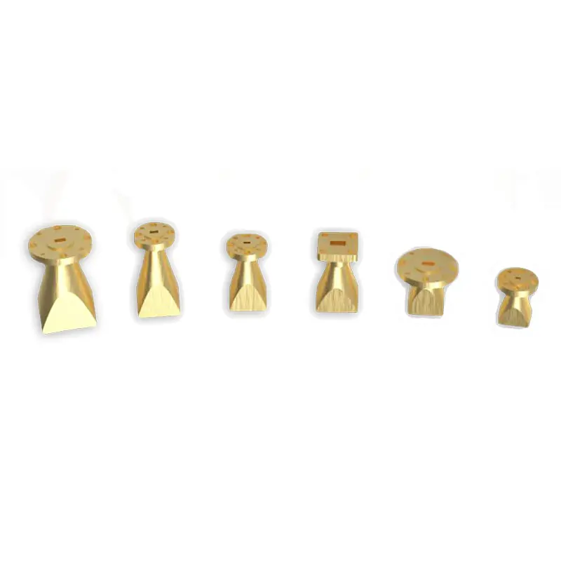
Standard Gain Horn Antenna
A Standard Gain Horn Antenna is a precision device widely used in electromagnetic field measurements and microwave testing. It offers a known gain at specific frequencies, making it ideal for calibrating other antennas, system testing, and as a reference standard in laboratories and field testing environments.
Dolph Microwave presents its line of Standard Gain Horn Antennas, meticulously engineered for applications in emissions and immunity testing across a broad frequency range from 0.32 to 110 GHz. These antennas are renowned for their high power handling, low loss, exceptional directivity, and consistent electrical performance over a wide bandwidth. Designed for precision, they are an indispensable tool in various testing and measurement scenarios.
Stable Reference Performance Across a Broad Microwave Range
The product family combines broad frequency coverage, selectable gain, practical interface options and durable construction for laboratory, chamber and field measurement setups.
Wide Frequency Range
Operation Frequency: Spanning from 0.32 to 110 GHz, catering to a vast array of testing requirements.
High Power Handling
Durability: Engineered to withstand high power levels, making them suitable for a range of demanding applications.
Exceptional Directivity and Low Loss
Performance: Offers high directivity and low loss, ensuring accurate and reliable measurements.
Consistent Electrical Performance
Stability: Near constant electrical performance across their operating bandwidth, with low gain variation.
Versatile Gain Options
Gain Values: Common gain values include 10, 15, 20, 25dB, with custom values available to meet specific needs.
Lightweight and Durable
Construction: Crafted to be lightweight and corrosion-resistant, ensuring longevity and ease of use.
Customizable Configurations
Adaptability: Available in configurations for waveguide mating, coaxial connector mating, or waveguide mounting with a coaxial adaptor fitted.
Select the Gain Class Around the Required Measurement Geometry
Common gain classes provide different nominal beamwidths. Lower-gain horns offer wider angular coverage, while higher-gain horns provide a narrower main beam for more directional measurements. Final selection should be based on the required operating band, test distance, chamber geometry and available mounting space.
| COMMON GAIN | NOMINAL 3 dB BEAMWIDTH | GENERAL CHARACTERISTIC |
|---|---|---|
| 10 dB | 55° | Wider beam coverage for general-purpose measurement arrangements. |
| 15 dB | 30° | Balanced directivity and physical size across many test setups. |
| 20 dB | 18° | Narrower beam for more directional reference and measurement work. |
| 25 dB | 10° | Highest common gain option with the narrowest listed nominal beamwidth. |
Gain and 3 dB beamwidth values are model dependent. Confirm the applicable model data and acceptance requirements before ordering.
Do Not Select by Gain Alone
A higher gain value is not automatically the better choice. A valid selection also depends on:
- Required operating frequency range
- Available far-field or test distance
- Desired angular coverage and directivity
- Waveguide or coaxial interface
- Flange standard and connector type
- Mechanical envelope and mounting method
- Required power-handling and test documentation
Choose the Interface That Matches the Test System
The antenna family supports waveguide and coaxial connection approaches so the horn can be integrated into different RF chains, chamber fixtures and laboratory instruments.
Waveguide Input
Direct waveguide mating is suitable when the antenna is connected to a matching waveguide transmission path. State the required IEC or EIA waveguide size and flange designation in the RFQ.
Built-in Coaxial Input
A built-in coaxial interface can simplify connection to compatible coaxial test equipment. Connector availability depends on frequency, gain class and the selected model.
Waveguide Mounting with Coaxial Adaptor
This configuration combines the horn and waveguide interface with a fitted coaxial adaptor, supporting system integration where a coaxial connection is required at the equipment side.
Model Availability Varies by Gain and Input Style
The stated 0.32 to 110 GHz range describes the product family rather than one single antenna. Each horn covers a defined waveguide band, and not every gain or input configuration is available across the entire portfolio range.
Portfolio-Level Range
The broad product family is presented for operation from 0.32 to 110 GHz. The downloadable catalog includes multiple waveguide families and gain classes, allowing selection by band rather than treating one horn as an ultra-wideband antenna.
Waveguide Family Confirmation
The existing product specification example lists waveguide sizes from WR-2300 to WR-28. Confirm the exact model, waveguide size, flange, gain and input arrangement before quotation.
Typical Standard Gain Horn Antenna Uses
The Dolph Microwave Standard Gain Horn Antenna is ideal for:
EMI/EMC Testing
Essential for electromagnetic compatibility testing, providing reliable data on emissions and immunity.
Antenna Gain Measurements
Accurately measures the gain of other antennas, serving as a reference standard.
Direction Finding
Useful in surveillance and security applications for pinpointing signal origins.
Surveillance
Assists in monitoring and gathering intelligence across wide frequency bands.
Scientific Research
Supports experiments and studies in electromagnetic field measurements.
Five Inputs Needed for a Reliable Preliminary Selection
A useful quotation starts with the measurement requirement, not only a requested gain value. The following sequence reduces the risk of selecting an incompatible band, flange or mechanical configuration.
Define the Band
Provide the minimum and maximum operating frequencies and identify whether full-band coverage is required.
Select Gain
Choose the required gain and nominal beamwidth around the measurement distance and angular coverage.
Choose Input Style
State waveguide input, built-in coaxial input or waveguide mounting with a fitted coaxial adaptor.
Confirm Interfaces
Specify waveguide size, flange type, connector type, connector gender and mating requirements.
Review Mechanics
Confirm mounting, available envelope, finish, quantity and any required test or dimensional documentation.
Published Product Family Summary
To provide an insight into our product offerings, here is an example specification table:
| SPECIFICATION | DETAIL |
|---|---|
| Frequency Range | 0.32 to 110 GHz |
| Waveguide Sizes | WR-2300 to WR-28 |
| Common Gain Values | 10, 15, 20, 25dB |
| 3dB Beamwidth | 10°, 18°, 30°, 55° |
| Configurations | Waveguide mating, coaxial connector, coaxial adaptor fitted |
This is a product-family example rather than a complete model table. Frequency range, gain, beamwidth, dimensions, waveguide size, flange and connector must be confirmed against the selected model and approved quotation.
Dolph Microwave’s Standard Gain Horn Antennas stand out for their precision, reliability, and versatility, making them a cornerstone in the field of RF and microwave testing. Whether for standard applications or custom needs, our antennas are designed to deliver unparalleled performance.
Designed for Repeated Laboratory and Field Handling
The antenna family is described as lightweight and corrosion-resistant, supporting practical handling in laboratory, chamber and field measurement setups.
Where the antenna will be exposed to unusual temperature, humidity, outdoor handling, vibration or high-power conditions, include those requirements in the RFQ so the material, finish and interface can be reviewed for the intended use.
Documents to Define Before Order
- Approved model and part number
- Mechanical outline or interface drawing
- Flange or connector designation
- Electrical performance requirements
- Required test data or inspection records
- Quantity and delivery schedule
Configuration Review for Specific Measurement Requirements
We understand the unique requirements of our clients and offer customized solutions to fit specific measurement and testing needs. Our team of experienced engineers is dedicated to providing support and guidance, ensuring you select the perfect antenna configuration for your project.
For further details or to discuss your specific antenna requirements, please contact us. Dolph Microwave is committed to advancing your projects with our high-quality, precision-engineered RF solutions.
Information to Include with Your Request
Providing complete project inputs allows the engineering and sales team to review model suitability, interface compatibility and customization requirements more efficiently.
Specification and Flange Reference Documents
Use the antenna catalog for detailed model data and the flange document to verify the required mechanical interface.







