Waveguide Switches

Waveguide switches select RF paths between connected waveguide ports. Dolph offers manual and motorized configurations; specify the port-routing states, operating band, mating flanges and control requirements. State whether RF power will be removed before switching, because a steady-state power rating does not establish hot-switching capability.

Dolph Microwave – Waveguide routing

Specify the RF path and actuation before choosing the switch.

A waveguide switch changes which RF ports are connected, allowing equipment to select measurement paths, transmitter branches or redundant signal routes. Choose the port topology before the actuator. Insertion loss and VSWR apply to the selected path; isolation describes leakage into an unselected path and needs its own acceptance limit.

Request Switch Review
Operation
Manual or motorized
RF path
Configuration-specific
Interface
Waveguide and flange pair
Control
Confirm before quotation
Configuration inputs

Send the details that control the final configuration

01

Waveguide size

Provide the waveguide designation and operating band.

02

Switch topology

State the required ports and RF routing states.

03

Actuation

Manual or motorized, including the required control method.

04

Flange and envelope

Mating flange, orientation and available installation space.

Numeric performance is confirmed against the selected switch configuration.

Specify both steady-state RF power and the RF condition during motion. A switch approved to carry power in a settled position is not automatically approved to switch that power. Include CW or pulse conditions, required switching time, settling time and any RF interlock sequence.

Request Configuration Review
Engineering handoff

Include the control and fail-state requirement.

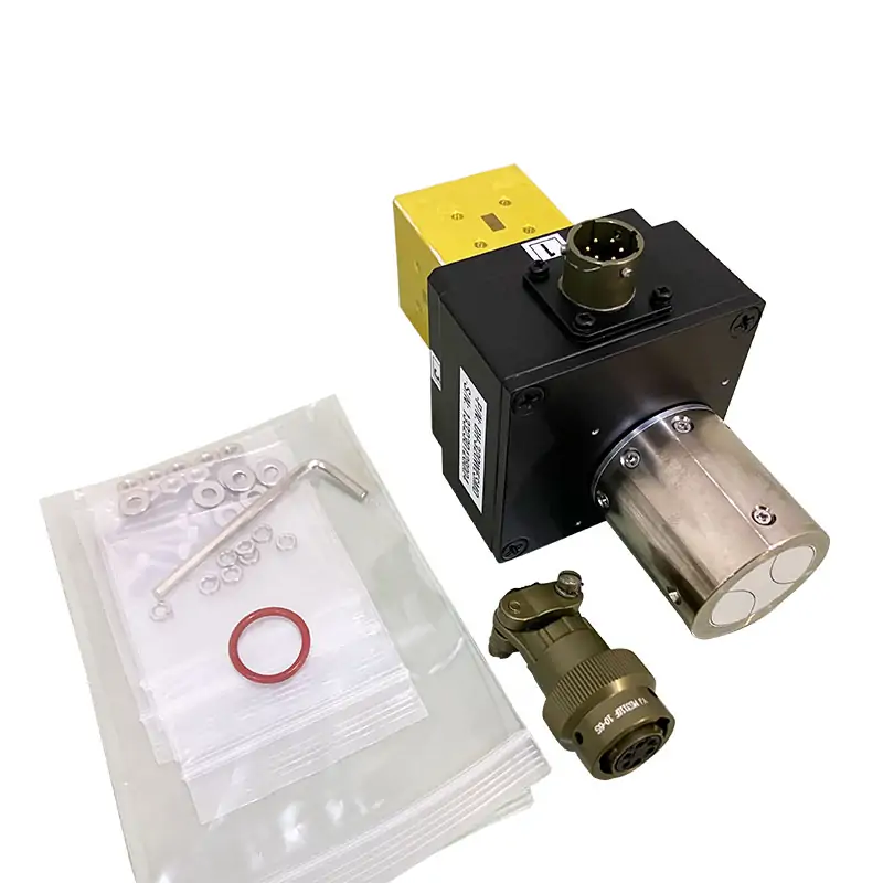
For a motorized switch, provide control voltage, command interface, position-indication needs and the required state after power loss. For a manual switch, define operator access and position identification. Confirm the port-state diagram and control pinout on the selected model drawing.

RFQ checklist

  • Waveguide size and operating band
  • Port count and switching topology
  • Manual/motorized actuation and control
  • Flange, envelope and environmental limits
Related RF path

Continue with the matching component family

Waveguide Transitions

Align different waveguide sizes or interfaces around the switch.

Double-Ridged Straights

Continue the RF path with drawing-controlled straight sections.

Quick-Release Joints

Add repeatable service access where required.

Ready for a model check?

Send the port-state diagram, operating band, waveguide and flange drawings, CW/peak power, switching sequence and control requirements. Include an interface drawing when the switch must fit an existing assembly.

Start an RFQ
Scroll to Top
Blank Form (#3)