
Waveguide power handling is limited by both heating and electrical breakdown. Check the continuous or average power, pulse peak power, operating frequency, gas pressure and cooling conditions separately. A low duty cycle reduces average power; it does not prove that the waveguide can withstand the pulse peak.
The calculations below are illustrative engineering examples, not Dolph product ratings or reports of customer projects. Use the rated limits and test conditions for the complete assembly, including its bends, flanges, windows, switches and terminations.
| Quantity | What to check |
|---|---|
| CW or average input power | Dissipated heat, local temperature and thermal steady state. |
| Peak input power | Electric-field stress, pulse duration, mismatch and breakdown margin. |
| Internal gas conditions | Absolute pressure, gas composition, moisture and the pressure range during operation. |
| Cooling | Heat load, ambient or coolant temperature, flow and loss-of-cooling protection. |
Continuous Wave Power and Peak Power
Table of Contents
What is Continuous Wave (CW) Power
CW describes continuous RF operation. A CW power rating is the maximum permitted continuous input under specified conditions. The two terms should not be confused: an operating power is a demand, while a rating is a limit.
Ask for the rating at the actual frequency, ambient temperature, internal pressure and cooling arrangement. A WR designation defines a waveguide size, not a universal power rating. Straight sections and a complete feed assembly can have different limits.
Example: splitting 5 kW into two paths. An ideal equal divider sends 2.5 kW to each output, but its input and the upstream waveguide still carry 5 kW. Each output also needs allowance for imbalance, mismatch and the agreed operating margin. Adding a divider does not make an upstream section rated for only 2.5 kW suitable for 5 kW.
Cooling must remove the power actually dissipated, rather than all the RF power transmitted. If reflection and leakage are negligible, a passive section with insertion loss L has an approximate heat load of Pheat = Pin[1 − 10−L/10]. This conversion follows the decibel definition for power ratios.[1]
At 5 kW input, illustrative losses of 0.05–0.20 dB correspond to roughly 57–225 W of heat under those assumptions. This is a calculated range, not a typical-loss specification. If reflection, radiation or additional ports are significant, separate those power paths before estimating internal heating.
What is Peak Power
For a pulsed RF signal, peak power refers here to the maximum pulse-envelope power, averaged over the RF carrier cycle. A peak-power rating also needs a specified pulse width, repetition rate, pressure, frequency and allowable mismatch.
A component can satisfy its average-power limit and still fail its peak-power limit. Conversely, an acceptable short-pulse peak rating does not establish that the same power can be transmitted continuously.
Field concentration at discontinuities, damaged surfaces or dielectric interfaces can make one component the limiting point in an otherwise suitable waveguide run. Check the complete RF path instead of applying a straight-waveguide rating to every part.
The Importance of Duty Cycle
For equal rectangular pulses with negligible RF power between pulses, D = τ × PRR and Paverage = Ppeak × D. Use pulse width τ in seconds and pulse repetition rate PRR in hertz. For shaped pulses or burst operation, calculate the time average of the actual power waveform.
| Pulse input | Calculated result |
|---|---|
| 50 kW peak; 0.5 μs at 1 kHz | 0.05% duty cycle; 25 W average power |
| 100 kW peak; 2 μs at 2 kHz | 0.4% duty cycle; 400 W average power |
Both examples still require separate peak-power verification. Neither 25 W nor 400 W of average transmitted power is the component’s heat load; that depends on its losses. Pulse duration and local thermal response also matter when assessing hot spots.
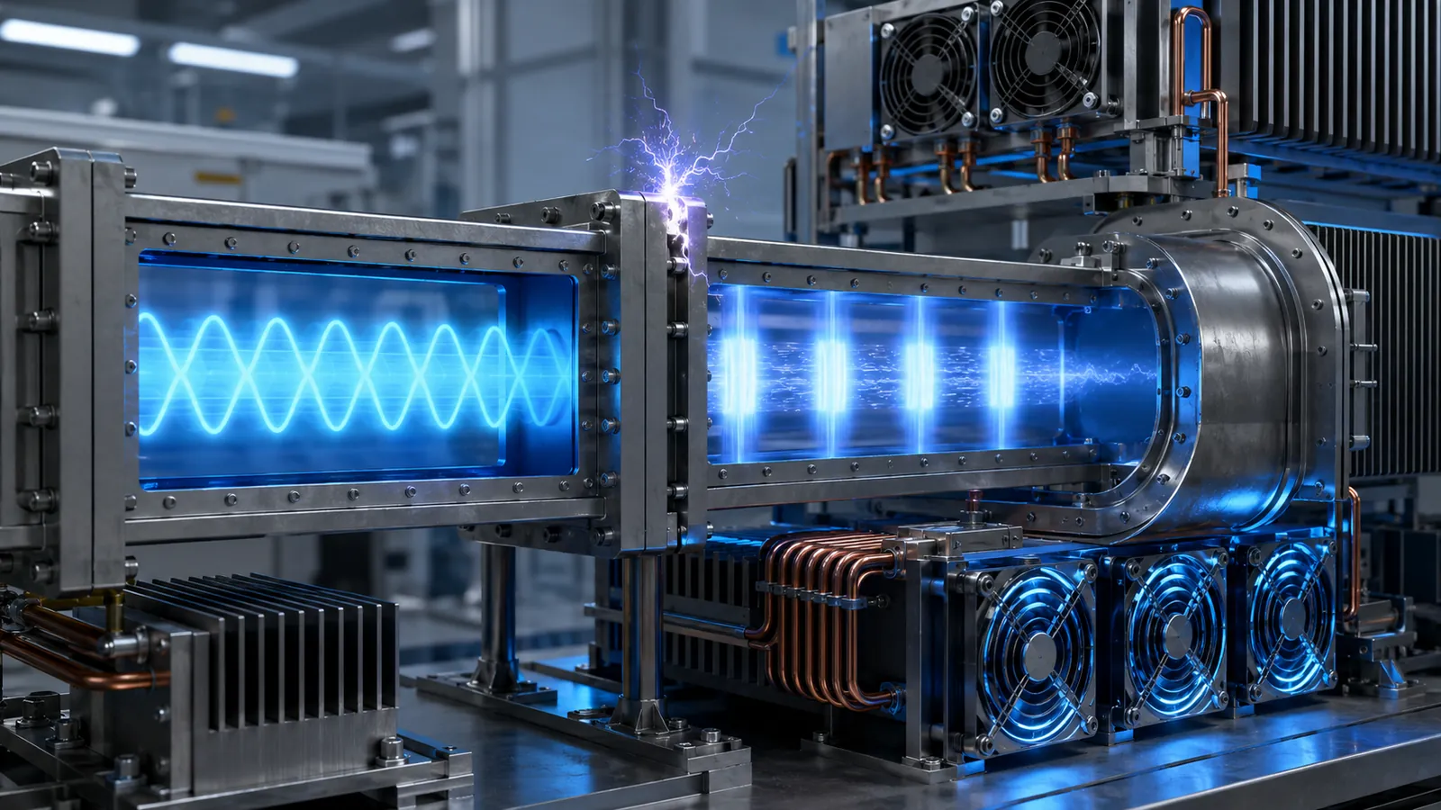
Breakdown Limits
Fundamentals of Voltage Breakdown
Gas ionization and vacuum multipactor are different RF breakdown mechanisms. NASA JPL tests for both and tailors the test conditions to the hardware. A pressure value or a single electric-field estimate cannot cover both mechanisms.[2]
Paschen-type gas-gap analysis relates breakdown behavior to gas pressure and gap size under specified assumptions. It is not a universal microwave power-rating formula. RF frequency, pulse duration, surface condition, geometry and mismatch must be included in the applicable analysis or test.
State the maximum permitted VSWR or reflected-power condition in the purchase specification. A rating demonstrated into a matched load may not apply when a disconnected, mistuned or failed downstream component creates a standing wave.
Altitude Derating
Altitude affects an unsealed waveguide through changing gas pressure and air-cooling conditions. NASA’s standard-atmosphere model gives approximately 60 kPa absolute at 4,200 m, compared with about 101.3 kPa at sea level. The pressure decrease is roughly 41%; it is not automatically a 41% reduction in allowable RF power.[3]
Use the assembly’s pressure-dependent rating or qualification data. Gas-breakdown behavior is nonlinear, and vacuum introduces a different assessment. For sealed equipment, distinguish internal absolute pressure from external ambient pressure and check the mechanical pressure difference across windows and seals.
The Role of Pressurized Waveguides
Dry-gas pressurization may improve the gas-breakdown margin and control moisture where the assembly is designed for it. Select the operating pressure from the complete assembly rating, including pressure windows, seals and connected instruments.
Specify whether every pressure value is gauge or absolute. For example, 100 kPa gauge is approximately 201 kPa absolute at sea-level atmospheric pressure. That conversion does not make 100 kPa gauge an acceptable setpoint for an unrated assembly.
The pressure inlet section must match the approved gas connection and seal. The system specification should also define pressure regulation, relief protection, dryness, leakage limits, alarms and the response to loss of pressure.
Express moisture requirements as a dew point at a stated pressure. A −40°C dew-point requirement, if selected for a project, must be compared with the coldest internal surface and the moisture-control margin; it is not a universal waveguide requirement.
Document the leak-test gas, pressure, temperature, measurement method and acceptance limit. NASA-STD-7012 provides a formal framework for leak testing spaceflight hardware; it does not assign a universal leakage limit to commercial waveguide assemblies.[4]
Cooling
Air Cooling Basics
Natural convection uses air movement caused by temperature differences. Forced-air cooling adds a fan. Compare their ability to remove the calculated heat at the worst ambient temperature, installation orientation and airflow restriction.
For a steady-state screening calculation, ΔT ≈ Pheat × Rθ, with thermal resistance in °C/W. If a hypothetical design permits a 35°C rise and dissipates 175 W, its total thermal resistance must be no more than about 0.20°C/W. Check local hot spots and temperature-dependent losses before treating this estimate as a validated design.
External cooling air does not normally need to pass through the RF aperture. Keep the cooling-air path separate from any controlled internal dry-gas system. Specify filters, maintenance access and fan-failure detection where the installation needs them.
Liquid Cooling Methods
Liquid cooling can remove concentrated heat through jackets, cooling plates or component-specific channels. Determine flow, coolant compatibility, pressure drop, inlet temperature and heat-exchanger capacity from the heat load.
A coolant energy balance is Q̇ = ṁcpΔT. For water near room temperature, using a density of approximately 1 kg/L and a specific heat of about 4.18 kJ/(kg·K), 40 L/min with a 15°C rise removes approximately 42 kW of heat. This is a calculated coolant duty, not a 42 kW RF input rating or a required flow for every waveguide.[5]
For a documented high-power comparison, ITER India reported tests at 170 GHz and 1 MW for 1,000-second pulses, using a purpose-built facility with an evacuated corrugated-waveguide path. These are ITER project results, not Dolph test results or ratings transferable to ordinary rectangular waveguide.[6]
Water-flow calculations alone do not establish component temperature. Check the thermal contact path, channel distribution, coolant pressure and local heat flux. Define interlocks for loss of flow, excessive temperature and leakage.
Choosing the Right Cooling Method
| Cooling option | Acceptance question |
|---|---|
| Natural convection | Do all parts stay below their temperature limits at the worst ambient condition without a fan? |
| Forced air | Is the required airflow maintained through the installed system, including filter loading and fan-failure conditions? |
| Liquid cooling | Can the coolant circuit and heat exchanger remove the heat while meeting flow, pressure, temperature and leak limits? |
A universal “air below 10 kW, liquid above 10 kW” rule misses the difference between transmitted power and dissipated heat. Use losses, allowable temperatures and the installed cooling path to choose the method.
Request an acceptance report that identifies the tested assembly, frequency, waveform, pressure, load match, cooling conditions, temperatures and agreed limits. A low-power VNA sweep verifies RF behavior under its test conditions; it does not establish a high-power rating.
For a custom waveguide assembly, include peak and average power, pulse timing, operating band, maximum mismatch, pressure, ambient temperature and cooling availability in the inquiry. Ask Dolph to confirm the rating and verification scope for that configuration before ordering.