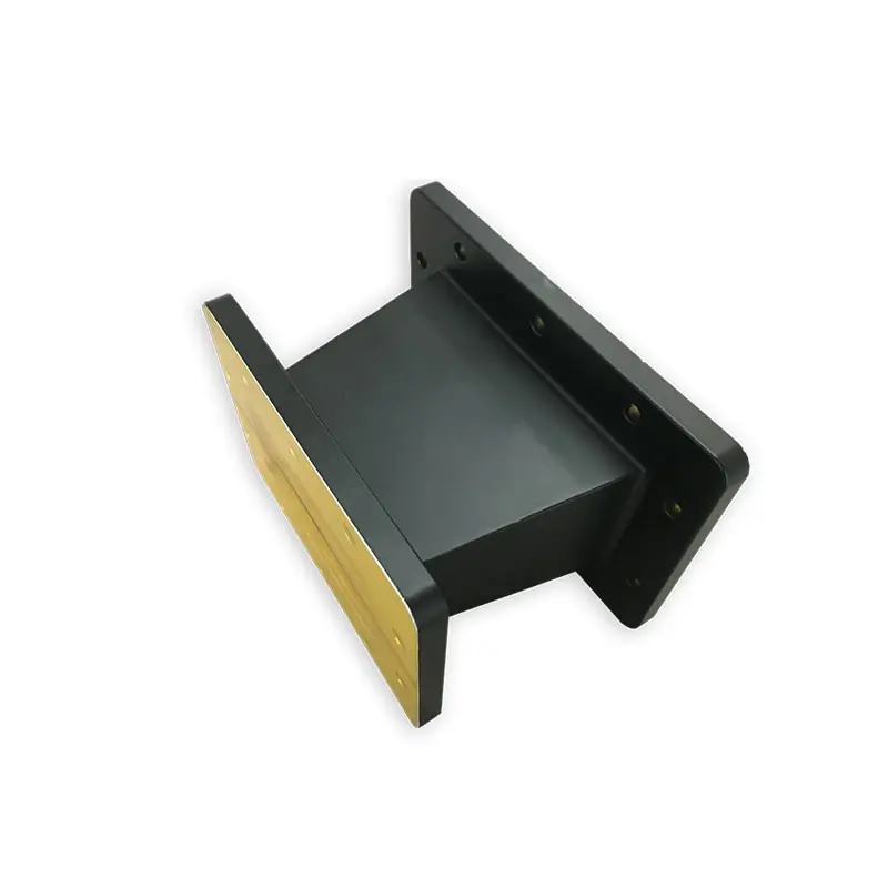
Dolph Microwave supplies tapered waveguide transitions for 915 MHz and 2450 MHz industrial microwave lines. Published options cover 6 KW, 10 KW and up to 20 KW CW, 100 mm and 200 mm lengths or other lengths on request, with Al/Cu material options. Send both waveguide interfaces, flange types, power and target length for configuration confirmation.
Match the Transition to Your Waveguide Line
For 915 MHz and 2450 MHz industrial microwave systems, specify both waveguide ends, flange faces, CW power and available length. Standard and custom lengths are available, and the final configuration can be checked against your drawing before production.
Frequency
915 MHz
2450 MHz
CW Power
6 KW, 10 KW
up to 20 KW
Length
100 mm, 200 mm
or others
Materials
Al, Cu
Current 2450 MHz Taper Models
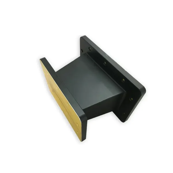
The current product datasheet lists the two taper configurations below. Model, WR type, frequency, VSWR and standard size are kept exactly as published.
| Model | WR Type | Frequency (MHz) | VSWR Max. | STD.Size (mm) |
|---|---|---|---|---|
| DH-22T26WA… | WR430T340 | 2450 | 1.1 | 100 |
| DH-32T26WA… | WR284T340 | 2450 | 1.1 | 100 |
Ordering Code
Use the published code when the configuration matches your line. For a different interface pair or installation length, send your drawing instead.
DH – 22T26 WA 100 P M A
Flange, Finish and Material Data
The finish table below is kept exactly as listed for the current 2450 MHz models. For mating flange codes beyond Cover/Grooved, use the waveguide flange size guide and the flange PDF at the bottom of this page.
| Flange Type | Inside Finish | Body Finish | Material |
|---|---|---|---|
| Cover/Grooved | Iridite per MIL-C-5541 | Anticorrosion Black Painted | Al/Brass |
| Cover/Grooved | Iridite per MIL-C-5541 | Anticorrosion Black Painted | Al/Brass |
What to Send With Your RFQ
A drawing is preferred when flange position or available space is fixed. For a fast model check, include the details below.
Operating frequency
915 MHz, 2450 MHz or the required band.
CW power
State the continuous power requirement.
Both waveguide ends
Give the WR or IEC designation at each end.
Flange pair
Cover, grooved or exact flange designation.
Overall length
Use 100 mm, 200 mm or your available space.
Drawing and quantity
Add interface dimensions, quantity and required delivery timing.
When the Published Pair Is Not Your Interface
The industrial microwave datasheet shows WR430 to WR340 and WR284 to WR340 taper models at 2450 MHz. For other waveguide pairs, other bands or a rectangular-to-circular interface, use the matching transition family below and send both mating ends for confirmation.
Other Waveguide Pairs
For standard rectangular transitions outside the two industrial models, review the broader waveguide transition range.
View Waveguide TransitionsRectangular to Circular
If one side is circular waveguide, use the rectangular-to-circular transition family rather than this industrial taper model.
View Rectangular-to-Circular ModelsCustom Industrial Line
For transitions supplied together with tuners, isolators, bends, couplers or loads, review the industrial microwave component range.
View Custom Industrial Microwave ComponentsFactory and Quality Basis
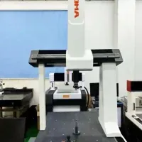
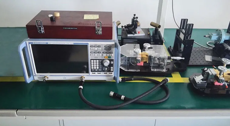
Dolph Microwave states that it has operated since 2001, works under an ISO 9001:2015 quality system and provides a one-year warranty against defective material and workmanship. Manufacturing resources also show coordinate measuring equipment and microwave testing facilities.
For a custom transition, state the dimensional checks, RF acceptance limits and report requirements you need with the RFQ so the inspection scope can be confirmed before order release.



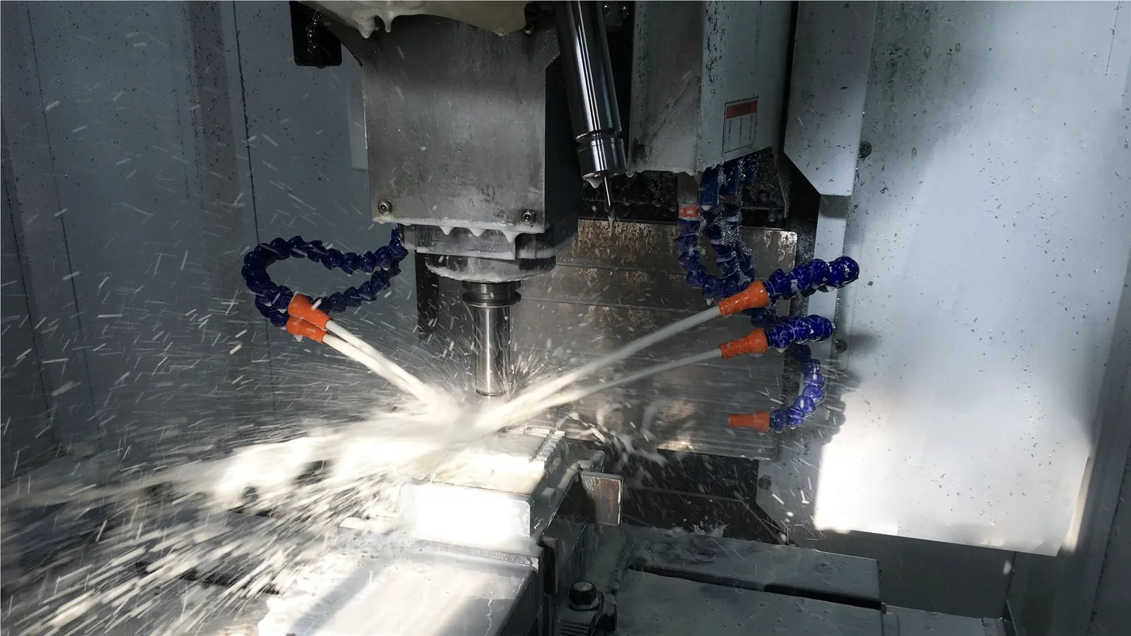
Components That Work With the Same Line
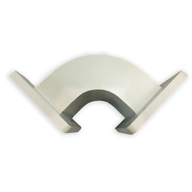
Need to Change Direction?
Use a microwave bend when the waveguide size stays the same but the route changes.
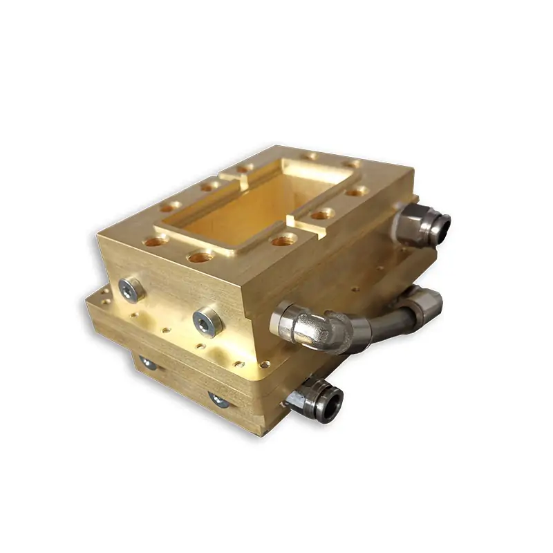
Need a Sealed Waveguide Interface?
Use a waveguide pressure window when the line must remain sealed while microwave power passes through.
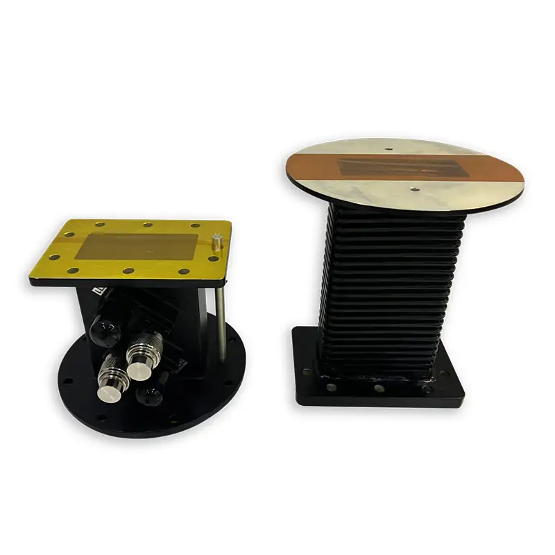
Need Power Sampling or Monitoring?
Use a microwave coupler when you need a sampled signal rather than a change in waveguide size.
Have the Waveguide Sizes but Not the Exact Part Number?
Send both waveguide ends, flange types, frequency, CW power and target length. Dolph Microwave can check the published model first and review a custom configuration when needed.
Useful Engineering References
Use these when checking the rest of the waveguide line before you send the RFQ.
Technical Downloads
Use the transition datasheet for the current industrial models and the flange reference for IEC/EIA flange designations.