
Straight Waveguide Section
Use for a rigid, straight connection between two compatible waveguide interfaces of the same selected size.
Constant size · No bend · Fixed length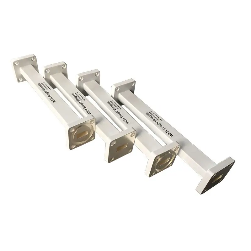
Straight waveguide sections are fundamental components in microwave and RF systems, designed to transmit electromagnetic waves between devices with minimal loss. They are precisely manufactured to maintain signal integrity and are available in various sizes and materials to suit specific frequency ranges and system requirements.
A straight waveguide section is intended for a constant-size transmission path without a directional change. When routing, orientation or interface conditions change, combine it with the appropriate waveguide component rather than forcing one component to perform several different functions.
Use for a rigid, straight connection between two compatible waveguide interfaces of the same selected size.
Constant size · No bend · Fixed lengthUse when the rigid transmission route must change direction while retaining the selected waveguide size.
View waveguide bends →Use when two system sections have different waveguide sizes, cross-sections or mechanical interfaces.
View waveguide transitions →Use where installation tolerances, vibration, alignment correction or constrained routing make a fully rigid connection unsuitable.
View flexible waveguides →Use where the rectangular waveguide path must connect to a coaxial cable, connector or RF instrument port.
View waveguide adapters →Use when the required route combines straights, bends, twists, flexible sections, adapters or nonstandard end interfaces.
View custom assemblies →The product range references aluminum 6061 and oxygen-free hard copper, together with painted copper-alloy and gold-plated options. The selected construction should be confirmed against frequency, weight, corrosion environment, handling and required finish.
At higher microwave and millimeter-wave frequencies, the electrical condition of the internal conducting surface becomes increasingly important. Material and plating should therefore be specified together with the operating band and acceptance requirements.
Read the millimeter-wave guide →Referenced for lightweight waveguide construction. Confirm the required corrosion protection, exterior finish and any internal plating requirement for the application.
Referenced where copper construction is preferred for electrical performance. Weight, mechanical support, joining method and exterior protection should be considered in the assembly design.
SurTec/corrosion protection and flat-black exterior paint are stated for standard models. Other finishes, colors and gold-plated options are available for review against the selected configuration.
The two ends of one straight section do not necessarily need to use the same flange configuration. Identify each mating component separately and state whether the connection requires a flat, cover, grooved or other published flange designation.
Match the hole pattern, aperture, flange family, alignment features and sealing groove to the adjoining equipment.
Select the sealing component according to the flange geometry and whether the joint requires pressure sealing, RF sealing or both.
State whether the waveguide run will be pressurized and identify the required pressure interface, sealing arrangement and leak-test requirement.
Allow sufficient space for flange hardware, tools, gasket placement, inspection and removal without forcing the waveguide alignment.
Protect the internal RF surfaces and flange faces from contamination, impact and deformation throughout storage, assembly and installation.
Check the model, WR size, flange designation, length and orientation against the approved drawing.
Inspect the aperture, flange faces, alignment features and sealing groove before assembly.
Remove loose particles and keep the waveguide interior dry using the project-approved cleaning procedure.
Bring mating flanges into alignment without using the fasteners to pull a misaligned rigid assembly into position.
Support the section so its weight does not distort the mating component or leave a rigid flange joint carrying unintended load.
Use the specified gasket or O-ring and confirm that it is seated correctly without entering the waveguide aperture.
Tighten the approved hardware gradually and evenly according to the equipment or project assembly specification.
Confirm mechanical clearance, support, flange contact, fastener condition and the absence of visible gaps or distortion.
Complete the required leak, continuity, dimensional or RF verification after installation and record the result when project documentation requires it.
Dolph Microwave’s custom-assembly information covers L, S, C, X, Ku, K and Ka bands through high millimeter-wave W-band frequencies.
Published options include oxygen-free copper construction, brazed assemblies, bendable or twistable sections and project-specific end flanges. Custom work can begin from a detailed drawing or an initial sketch for technical review.
Explore custom waveguide assemblies →High-frequency, high-power, pressurized, outdoor, vacuum or aerospace systems may require additional design and verification beyond the standard model description.
Confirm internal surface quality, material, plating, flange alignment and the required measurement method for the selected high-frequency model.
State average power, peak power, duty cycle, operating environment, pressure condition and any required conditioning or arc-detection procedure.
Confirm the gas or dry-air arrangement, operating pressure, pressure inlet, gasket selection, leak requirement and monitoring method.
Space-qualified and vacuum-related requirements require a separate project review. A standard straight-waveguide model should not be assumed to meet a space qualification without documented confirmation.
Review these related topics when the straight section forms part of a larger waveguide assembly, pressurized system, millimeter-wave path or coaxial interface.
Additional guidance covering dimensions, flange selection, sealing, thermal considerations and mounting alignment.
Review frequency range, coaxial connector, RF requirements, construction and installation compatibility.
Understand which component is used when the RF path must change direction or orientation.
Additional context for impedance matching, mechanical integration and material considerations.
The straight section can be reviewed more efficiently when the RF, mechanical, material, sealing and documentation requirements are submitted together.







