
Waveguide size
Published WFA models span WR770, WR650, WR510, WR430, WR340, WR284, WR229, WR187, WR159, WR137, WR112, WR90, WR75, WR62, WR51, WR42, WR34, WR28, WR22, WR19, WR15, WR12 and WR10.
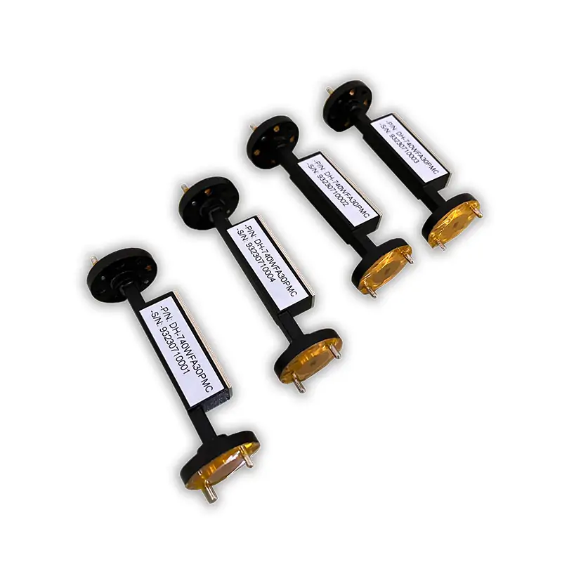
Waveguide fixed attenuators are essential components in microwave systems, designed to reduce signal power uniformly without affecting its waveform. They provide precise attenuation for signal control in various applications, including telecommunications, radar systems, and electronic testing, ensuring optimal system performance and reliability.
Dolph Microwave WFA series fixed attenuators provide defined signal reduction for standard rectangular waveguide systems from 0.96 to 112 GHz. Published models offer a maximum VSWR of 1.15:1, attenuation values from 3 to 40 dB, ±1.0 dB frequency response, model-dependent 100 to 3000 W CW power handling, aluminum or copper construction, and cover or grooved flange configurations. Broader WR2300-to-WR10, choke-flange and customized mechanical configurations are available subject to engineering review.
A waveguide fixed attenuator introduces a specified amount of attenuation into the transmission path without requiring field adjustment. It is used where the required signal reduction is known in advance and must remain mechanically stable after installation.
Published WFA models cover 0.96–112 GHz and WR770–WR10. The broader product-family description also identifies WR2300–WR10 availability, including fixed, variable, cover, grooved and choke-flange configurations. Requirements outside the published WFA matrix should be reviewed as a custom or related attenuator configuration.
Frequency coverage in the published online WFA matrix.
Broader WR2300–WR10 family configurations are subject to confirmation.
Commonly referenced values include 10, 20, 30 and 40 dB.
Published online value; approved model documentation governs.
Frequency band alone is not sufficient for model selection. Attenuation value, CW power, flange pair, material, finish and mechanical envelope should be specified together.
Published WFA models span WR770, WR650, WR510, WR430, WR340, WR284, WR229, WR187, WR159, WR137, WR112, WR90, WR75, WR62, WR51, WR42, WR34, WR28, WR22, WR19, WR15, WR12 and WR10.
The online matrix lists 3–40 dB. The general product description highlights 10, 20, 30 and 40 dB as common selections, while the brochure reference table lists 3–30 dB.
Published values range from 100 to 3000 W CW depending on waveguide size and model. The final rating must be confirmed together with attenuation, duty conditions, cooling and installation environment.
The published table uses aluminum for WR770 through WR28 models and copper for WR22 through WR10 models. Alternative materials should be treated as an engineered option.
Cover and grooved flange designations are included in the model table. The wider family description also lists choke flanges. Each end can be specified separately where a mixed flange pair is required.
Standard configurations can be selected from the published matrix. Custom mechanical layouts, finishes, paint colors and related attenuation configurations can be reviewed against the required system interface.
Fixed attenuation is appropriate when the required signal reduction is established during system design and does not need continuous adjustment during operation.
Need field adjustment? Read about variable attenuators →Establishing a defined signal level in microwave communication links and transmission paths.
Reducing a known signal level before a receiver, monitoring branch or other system stage.
Creating repeatable attenuation conditions for component, subsystem and laboratory evaluations.
Managing signal levels within waveguide feed, ground-station and associated RF transmission assemblies.
Providing a stable attenuation element for prototypes, experimental benches and characterized test paths.
Power values are displayed as W CW. Final electrical performance, dimensions, attenuation tolerance and power rating must be confirmed on the approved quotation and model drawing.
| Model | Frequency Range | WG Size | VSWR Max. | Attenuation | Frequency Response | Published CW Power | Cover Flange | Grooved Flange | Material | Finish | Files |
|---|---|---|---|---|---|---|---|---|---|---|---|
| DH-12WFA… | 0.96–1.46 GHz | WR770 | 1.15:1 | 3–40 dB | ±1.0 dB | 100–3000 W CW | UDR12 | PDR12 | Al | Chromate / Painted | Request DWG / STEP |
| DH-14WFA… | 1.13–1.73 GHz | WR650 | 1.15:1 | 3–40 dB | ±1.0 dB | 100–3000 W CW | UDR14 | PDR14 | Al | Chromate / Painted | Request DWG / STEP |
| DH-18WFA… | 1.45–2.20 GHz | WR510 | 1.15:1 | 3–40 dB | ±1.0 dB | 100–3000 W CW | UDR18 | PDR18 | Al | Chromate / Painted | Request DWG / STEP |
| DH-22WFA… | 1.72–2.61 GHz | WR430 | 1.15:1 | 3–40 dB | ±1.0 dB | 100–3000 W CW | UDR22 | PDR22 | Al | Chromate / Painted | Request DWG / STEP |
| DH-26WFA… | 2.17–3.30 GHz | WR340 | 1.15:1 | 3–40 dB | ±1.0 dB | 100–3000 W CW | UDR26 | PDR26 | Al | Chromate / Painted | Request DWG / STEP |
| DH-32WFA… | 2.60–3.95 GHz | WR284 | 1.15:1 | 3–40 dB | ±1.0 dB | 100–3000 W CW | UDR32 | PDR32 | Al | Chromate / Painted | Request DWG / STEP |
| DH-40WFA… | 3.22–4.90 GHz | WR229 | 1.15:1 | 3–40 dB | ±1.0 dB | 100–3000 W CW | UDR40 | PDR40 | Al | Chromate / Painted | Request DWG / STEP |
| DH-48WFA… | 3.94–5.99 GHz | WR187 | 1.15:1 | 3–40 dB | ±1.0 dB | 100–3000 W CW | UDR48 | PDR48* | Al | Chromate / Painted | Request DWG / STEP |
| DH-58WFA… | 4.64–7.05 GHz | WR159 | 1.15:1 | 3–40 dB | ±1.0 dB | 100–2000 W CW | UDR58 | PDR58 | Al | Chromate / Painted | Request DWG / STEP |
| DH-70WFA… | 5.38–8.17 GHz | WR137 | 1.15:1 | 3–40 dB | ±1.0 dB | 100–2000 W CW | UDR70 | PDR70 | Al | Chromate / Painted | Request DWG / STEP |
| DH-84WFA… | 6.57–9.99 GHz | WR112 | 1.15:1 | 3–40 dB | ±1.0 dB | 100–2000 W CW | UDR84 / UBR84 | PDR84 / PBR84 | Al | Chromate / Painted | Request DWG / STEP |
| DH-100WFA… | 8.20–12.50 GHz | WR90 | 1.15:1 | 3–40 dB | ±1.0 dB | 100–2000 W CW | UDR100 / UBR100 | PDR100 / PBR100 | Al | Chromate / Painted | Request DWG / STEP |
| DH-120WFA… | 9.84–15.00 GHz | WR75* | 1.15:1 | 3–40 dB | ±1.0 dB | 100–1000 W CW | UDR120 / UBR120* | PDR120 / PBR120* | Al | Chromate / Painted | Request DWG / STEP |
| DH-140WFA… | 11.90–18.00 GHz | WR62 | 1.15:1 | 3–40 dB | ±1.0 dB | 100–1000 W CW | UBR140 | PBR140 | Al | Chromate / Painted | Request DWG / STEP |
| DH-180WFA… | 14.50–22.00 GHz | WR51 | 1.15:1 | 3–40 dB | ±1.0 dB | 100–1000 W CW | UBR180 | PBR180 | Al | Chromate / Painted | Request DWG / STEP |
| DH-220WFA… | 17.60–26.70 GHz | WR42 | 1.15:1 | 3–40 dB | ±1.0 dB | 100–1000 W CW | UBR220 | PBR220 | Al | Chromate / Painted | Request DWG / STEP |
| DH-260WFA… | 21.70–33.00 GHz | WR34 | 1.15:1 | 3–40 dB | ±1.0 dB | 100–500 W CW | UBR260 | PBR260 | Al | Chromate / Painted | Request DWG / STEP |
| DH-320WFA… | 26.30–40.00 GHz | WR28 | 1.15:1 | 3–40 dB | ±1.0 dB | 100–500 W CW | UBR320 | PBR320 | Al | Chromate / Painted | Request DWG / STEP |
| DH-400WFA… | 32.90–50.10 GHz | WR22 | 1.15:1 | 3–40 dB | ±1.0 dB | 100–500 W CW | FUGP400 / UG-383/U-M | — | Cu | Chromate / Painted | Request DWG / STEP |
| DH-500WFA… | 39.20–59.60 GHz | WR19 | 1.15:1 | 3–40 dB | ±1.0 dB | 100–500 W CW | FUGP500 / UG-383/U-M | — | Cu | Chromate / Painted | Request DWG / STEP |
| DH-620WFA… | 49.80–75.80 GHz | WR15 | 1.15:1 | 3–40 dB | ±1.0 dB | 100–500 W CW | FUGP620 / UG-385/U-M | — | Cu | Chromate / Painted | Request DWG / STEP |
| DH-740WFA… | 60.50–91.90 GHz | WR12 | 1.15:1 | 3–40 dB | ±1.0 dB | 100–500 W CW | FUGP740 / UG-387/U-M | — | Cu | Chromate / Painted | Request DWG / STEP |
| DH-900WFA… | 73.80–112.00 GHz | WR10 | 1.15:1 | 3–40 dB | ±1.0 dB | 100–500 W CW | FUGP900 / UG-387/U-M | — | Cu | Chromate / Painted | Request DWG / STEP |
This example identifies the waveguide size, attenuator family, nominal attenuation, two flange ends, material and CW power rating.
Dolph Microwave publishes flange-designation information covering cover, grooved and choke variants across multiple WR sizes.
Open flange designation PDF →Current WFA listings use aluminum in the lower and mid-band models and copper in the WR22-to-WR10 models.
Read the waveguide material guide →Published product information references corrosion-protection treatment, black painted exterior finishes and alternative finishing options subject to confirmation.
Dolph Microwave states that it supplies microwave devices, waveguide components, feed systems and related assemblies.
About Dolph Microwave →The company website provides an ISO 9001:2015 certificate covering the design, manufacture and sale of waveguide components.
View ISO certificate →Warranty coverage, remedies and exclusions are governed by the formal quotation and published terms and conditions.
Read terms and conditions →Providing complete operating and mechanical requirements reduces the risk of selecting the correct band but the wrong power, flange or installation configuration.
Review the separate high-power attenuator family where the standard WFA range is not suitable.
Match adjoining waveguide size, flange combination, material, finish and installation length.
Add a sampling interface where power monitoring or feedback is required alongside attenuation.
Review load and termination configurations for absorbing power at the end of a waveguide path.
Prepare a waveguide VNA measurement path for component verification and characterization.
Check flange families and interface designations before confirming a mixed waveguide assembly.
A fixed attenuator provides a predetermined attenuation value and does not require adjustment after installation. A variable attenuator is selected when the signal level must be changed during calibration, setup or operation.
The general product-family description states WR2300 to WR10. The currently published detailed WFA model table begins at WR770 and extends to WR10. WR2300 through WR975 requirements should be submitted for configuration confirmation.
They are highlighted as common values. The online matrix states a 3–40 dB range, while the downloadable brochure states 3–30 dB. State the exact required attenuation and allowable frequency response so the applicable model can be confirmed.
The part-number example uses separate positions for the first and second flange, allowing the flange at each end to be identified independently. Provide the complete mating-flange designation for both ports.
The values are presented here as watts CW. Do not select a model from the range alone; attenuation, frequency, ambient conditions and thermal installation must be reviewed together.
The product matrix references DWG and STEP documentation. Include the required drawing format, test data, inspection records and operating conditions with the RFQ so the deliverables can be confirmed before order placement.
Use the model-specific quotation, approved drawing and agreed technical documentation as the controlling specification. General catalog and website values should be treated as selection references.
Include the required operating band, nominal attenuation, CW and peak power, flange designation at both ends, preferred material, mechanical restrictions and requested drawings or test documents.







