
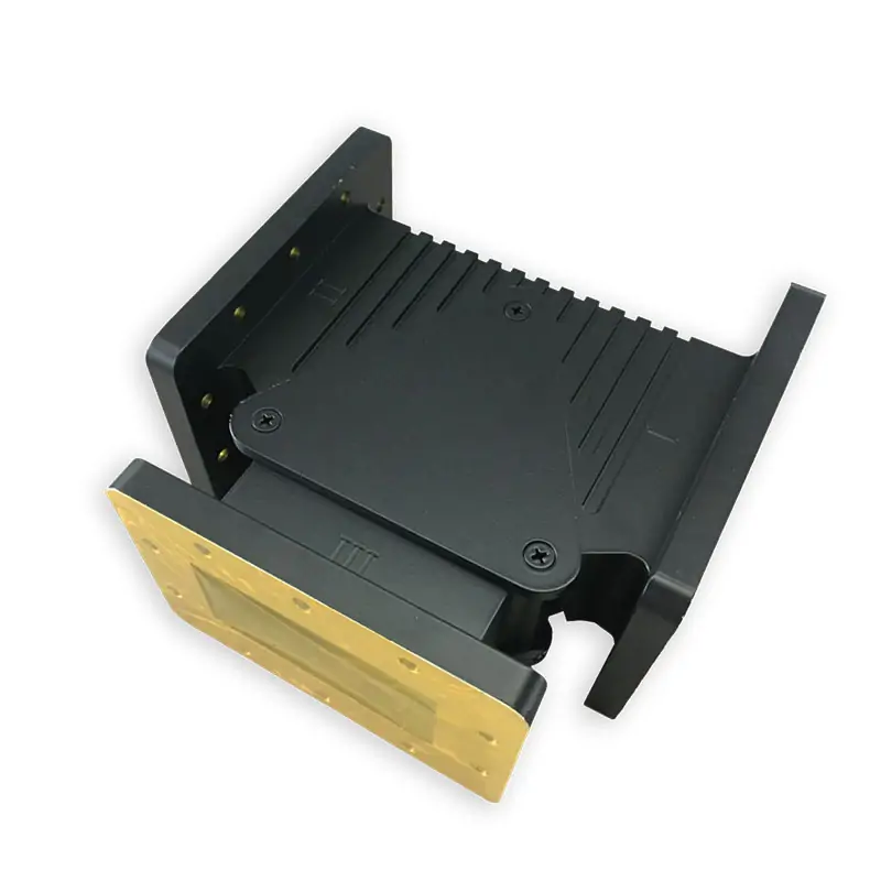
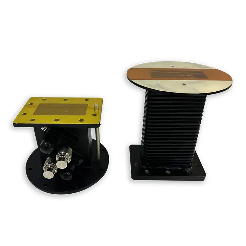
Dolph Microwave supplies waveguide circulators for high-power industrial microwave lines. The product datasheet lists WR975, WR650, WR430, WR340 and WR284 configurations at 915±25 MHz, 1300±25 MHz and 2450±25 MHz, with 1.2 VSWR, 0.25 dB insertion loss and 20 dB isolation in the published model matrix. Water-direct and air-cooled versions are listed by model. Send your frequency, power, waveguide size, flange, cooling and installation limits for model matching or a custom configuration.
Microwave Circulator Specifications
Use the published values below to confirm the base configuration before quotation. The standard feature block covers 915 MHz and 2450 MHz systems, while the product datasheet also lists 1300±25 MHz models and additional WR sizes.
Frequency range
915 MHz and 2450MHz
Waveguide size
WR340, WR430 and WR975
Handling power
6 KW, 10 KW, up to 20kW CW
Flange
Cover and Grooved
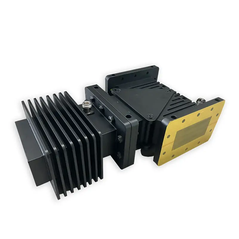
The three-port circulator routes reflected microwave power away from the source. Standard and customized configurations are available; the third port must be connected to the correct downstream component for the intended system layout.
Need the Right Model for Your Line?
Send frequency, forward power, reflected power, waveguide size and flange. We can match a listed model or review a custom build.
Model and RF Data
The rows below retain the model, configuration, waveguide, frequency, VSWR and insertion-loss values from the original product datasheet.
| Model | Config. | WR Type | Frequency (MHz) | VSWR | IL (dB) |
|---|---|---|---|---|---|
| DH-9WCIC915PPPA… | Circulator | WR975 | 915±25 | 1.2 | 0.25 |
| DH-9WCIC+WHC915PPPA… | Circulator+Coupler | WR975 | 915±25 | 1.2 | 0.25 |
| DH-14WCIC1300PPPA… | Circulator | WR650 | 1300±25 | 1.2 | 0.25 |
| DH-14WCIC+WHC1300PPPA… | Circulator+Coupler | WR650 | 1300±25 | 1.2 | 0.25 |
| DH-22WCIC2450PPPA… | Circulator | WR430 | 2450±25 | 1.2 | 0.25 |
| DH-26WCIC2450PPPA… | Circulator | WR340 | 2450±25 | 1.2 | 0.25 |
| DH-26WCIC+WHC2450PPPA… | Circulator+Coupler | WR340 | 2450±25 | 1.2 | 0.25 |
| DH-32WCIC2450PPPA… | Circulator | WR284 | 2450±25 | 1.2 | 0.25 |
| DH-32WCIC2450PPPA… | Circulator | WR284 | 2450±25 | 1.2 | 0.25 |
| DH-32WCIC+WHC2450PPPA… | Circulator+Coupler | WR284 | 2450±25 | 1.2 | 0.25 |
Power, Cooling and Mechanical Data
These values are model-specific. Do not select cooling or power handling from the feature block alone; match the required row to the frequency, waveguide and mechanical envelope.
Published isolation: 20 dB across the listed rows. Coupling values of 30-60 dB appear on Circulator+Coupler configurations.
| Isolation (dB) | Coupling (dB) | Handling Power (KW) | Cooling | Water Flow | Water Pressure | Water Injection | Size (mm) |
|---|---|---|---|---|---|---|---|
| 20 | 20-75-100 | Water-Direct | 3-5L/min | 0.14MPa | Quick Connector | 511*852*213 | |
| 20 | 30-60 | 20-75-100 | Water-Direct | 3-5L/min | 0.14MPa | Quick Connector | 511*852*213 |
| 20 | 10 | Water-Direct | 3-5L/min | 0.14MPa | Quick Connector | 350*580*170 | |
| 20 | 30-60 | 10 | Water-Direct | 3-5L/min | 0.14MPa | Quick Connector | 350*580*170 |
| 20 | 2 | Air | 220*380*106 | ||||
| 20 | 3-5-6-15 | Water-Direct | 3-5L/min | 0.14MPa | Quick Connector | 183*335*112 | |
| 20 | 30-60 | 3-5-6-15 | Water-Direct | 3-5L/min | 0.14MPa | Quick Connector | 183*335*112 |
| 20 | 3 | Air | 183*335*95 | ||||
| 20 | 6 | Water-Direct | 3-5L/min | 0.14MPa | Quick Connector | 183*335*112 | |
| 20 | 30-60 | 3-5-6-15 | Water-Direct | 3-5L/min | 0.14MPa | Quick Connector | 183*335*112 |
For high CW or pulsed operation, confirm the actual duty cycle, reflected-power condition and cooling before release. Dolph’s waveguide power handling guide explains the checks used for CW, peak power and cooling.
Review Power and CoolingFlange, Finish and Ordering Code
Keep the flange and ordering information tied to the actual mating waveguide. For EIA and IEC references, use Dolph’s waveguide flange size guide or the flange PDF at the bottom of this page.
| Flange Type | Inside Finish | Body Finish | Material |
|---|---|---|---|
| Cover/Grooved | Iridite per MIL-C-5541 | Anticorrosion Black Painted | Al |
| Cover/Grooved | Iridite per MIL-C-5541 | Anticorrosion Black Painted | Al |
| Cover/Grooved | Iridite per MIL-C-5541 | Anticorrosion Black Painted | Al |
| Cover/Grooved | Iridite per MIL-C-5541 | Anticorrosion Black Painted | Al |
Ordering Code Reference
| DH | Dolph Microwave |
| 26 | Waveguide Type WR340 |
| WCIC | Waveguide Circulator |
| 2450 | Freq. 2450 MHz |
| P | Flange Cover |
| M | Flange Grooved |
| A | Material Al |
| 6KW | Handling Power 6KW CW |
Send These Details for Model Matching
A useful RFQ is short. Send the actual operating values below and Dolph can match a standard model or define the required changes.
Frequency and bandwidth
Center frequency and allowed tolerance.
Forward and reflected power
CW power, peak power and duty cycle if pulsed.
Waveguide and flange
WR size and both mating flange types.
Cooling available
Air cooling or water supply, including flow and pressure limits.
Installation envelope
Maximum length, width, height and port orientation.
Drawing or replacement part
Attach a drawing, existing part number or interface dimensions if available.
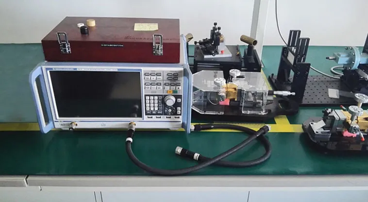
Built and Tested in Dolph Microwave’s Xi’an Facility
Machining, waveguide forming and bending, brazing, plating, assembly and RF testing are listed as in-house capabilities. Dolph’s published laboratory capability includes RF vector and scalar systems up to 100 GHz, antenna anechoic chambers and high-power transmitters.
Since 2001
Dolph Microwave manufacturing in Xi’an.
ISO 9001:2015
Published quality-system certification.
100 GHz
Published in-house RF measurement capability.
One-year warranty
Material and workmanship coverage under published terms.
Engineering References Before Release
Use these Dolph resources when the RFQ needs more than the standard product table.

Request a Circulator Quote
Send your frequency, power, waveguide, flange, cooling and size limits. Attach a drawing if the circulator must replace an existing part or fit a fixed installation envelope.
Technical Downloads
Download the original circulator datasheet and flange designation reference used for the technical values above.







