
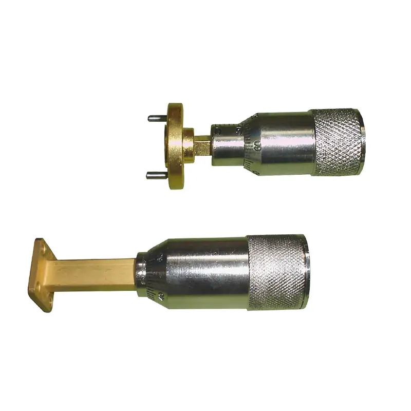
Waveguide Sliding Termination
A waveguide sliding termination is a precision device that enables the adjustment of the impedance match within a waveguide system. It slides along the waveguide to find the optimal position for minimal reflection, ensuring efficient energy transfer and improved system performance. This tool is essential for testing and measurement in microwave engineering.
Adjust the termination position without changing the waveguide run
The load slides inside a uniform waveguide section so its position can be adjusted during RF and microwave test, tuning and measurement work. Select the waveguide size, material and flange interface to match the surrounding hardware.
Send the interface details that affect fit and quotation
For a faster technical review, include the information below with your inquiry. A drawing or mating-flange reference is useful when the interface is not standard.
Waveguide Size
WR/R designation or target operating band.
Flange Interface
Cover, grooved or choke; add the mating standard or drawing when available.
Material
Aluminum (Al) or Copper (Cu).
Power & Quantity
Confirm the required CW power and order quantity.
Mechanical Requirement
Share any space, travel, mounting or drawing requirement for a custom configuration.
Published configuration range
The values below are retained from the existing Dolph Microwave product page. Confirm the final configuration before ordering.
This is the PDF link retained from the original product page.
| Parameter | Specification |
|---|---|
| Waveguide Size | WR2300 to WR10 |
| Power Handling | 10w cw |
| Material | Aluminum (Al) / Copper (Cu) |
| Flange Types | Cover, Grooved, Choke |
A movable load for controlled test and tuning work
RF & Microwave Test Benches
Change the load position while checking the behavior of a compatible waveguide setup.
Calibration & Measurement Work
Use controlled position changes where an adjustable termination is required by the measurement arrangement.
R&D and Verification
Suitable for component development, troubleshooting and repeatable waveguide experiments.
Radar, Satcom & Telecom Engineering
Use in engineering and test setups when the waveguide interface and published power range match the project.
Engineering support backed by Dolph’s waveguide manufacturing capability
Dolph Microwave states that it was founded in 2001 and references ISO 9001:2015 in its Quality Manual and Quality Procedure. The company also publishes a one-year warranty from delivery against defective material and workmanship.
CNC machining plus lathe and turning facilities are listed among Dolph’s manufacturing capabilities.
Waveguide forming and bending are included in the published process capability.
Brazing, soldering and assembly capabilities support microwave component production.
Dolph lists plating, anodising and passivation among its available manufacturing processes.
Choose the component and interface that match the job
Use when the requirement is a movable short-circuit for phase or electrical-length adjustment rather than a sliding matched load.
Review the fixed termination range when a movable load position is not required.
Check the mating flange family before finalizing the termination interface.
Related hardware for waveguide calibration and measurement setups.
Technical article covering EIA/IEC flange matching and gasket-fit considerations.
Review custom waveguide assembly support when the termination must fit a wider project-specific layout.
Confirm the part against your actual waveguide interface
The published sliding termination range is 10 W CW. If your project needs a different power level, a fixed termination, a high-power load or a different flange arrangement, send the requirement before placing the order so the correct product family can be reviewed.
Can I request a custom mechanical configuration?
Yes. The product page lists both standard and custom mechanical configurations. Send the waveguide size, flange details, material and mechanical requirement for review.
Which flange types are listed for this product?
Cover, Grooved and Choke. If you have an EIA/IEC designation or mating-part drawing, include it with the RFQ.
Is this the right part for higher power?
The published sliding termination page lists 10 W CW. For requirements above that value, review the waveguide termination range or ask Dolph to confirm the appropriate load design.
Send your waveguide size, flange, material, power and quantity
Add a drawing or mating-part reference when available. Dolph can review a standard or custom mechanical configuration against the information you provide.
Send Your RFQ →






