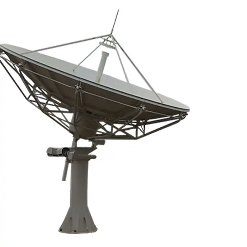
3.7 m / 4.5 m Dual-Reflector Earth Station Antenna System for Ku-Band Tx/Rx
Ring-focus earth station antenna systems for fixed satellite uplink and downlink. Ku-band configurations cover 10.95–12.75 GHz receive and 13.75–14.5 GHz transmit, with WR-75 CPR interfaces, up to 2 kW transmit capability, 0.5 mm reflector RMS, and manual or motorized jack-screw drive. Dolph datasheets also list X- (Military/WGS), C- and Ka-band capabilities; the selected feed, band, polarization and project acceptance requirements are confirmed for each order.
Select the aperture from RF data, then confirm the site configuration
The 3.7 m and 4.5 m systems share the same ring-focus mechanical concept and Ku-band frequency plan. The 4.5 m version provides higher gain and narrower beamwidth; the 3.7 m version keeps the same 2 kW transmit rating and WR-75 CPR interface in the Ku-band datasheet.
Product Configuration Overview
The table below summarizes the standard 3.7 m and 4.5 m configurations. Detailed datasheet values are listed separately below.
Wind-option wording and ITU-RS.580 revision references differ between the summary specifications and downloadable datasheets. Confirm the exact wind design basis, applicable standard revision and satellite-operator approval status for the ordered configuration.
| Parameter | 3.7 Meter Specifications | 4.5 Meter Specifications |
|---|---|---|
| Frequency Band | Ku | Ku |
| Reflector Design | Dual-Reflector Ring Focus | Dual-Reflector Ring Focus |
| Pedestal Type | Azimuth over Elevation | Azimuth over Elevation |
| Wind Survival | 125 Mph Standard, 180 Mph High Wind Option | 125 Mph Standard, 180 Mph High Wind Option |
| Feed Options | LP Adjustable, Multiple Configurations | LP Adjustable, Multiple Configurations |
| Regulatory Compliance | FCC, IESS, ITU-RS.580-5, Intelsat, Asiasat, APT, Chinasat | FCC, IESS, ITU-RS.580-5, Intelsat, Asiasat, APT, Chinasat |
Key Product Features
Dual-Reflector Design: Incorporates a main reflector and a sub-reflector within a ring focus structure, optimizing signal focus and minimizing noise for superior RF performance.
High-Stiffness Pedestal: The azimuth over elevation pedestal is designed for exceptional stability and stiffness, providing full orbital arc coverage and precise drive performance.
Ease of Alignment: Features stretch-formed doubly contoured panels with matched radials and hub, simplifying field alignment and installation.
Regulatory Compliance: Meets rigorous RF specifications, including FCC 25.209, IESS, ITU-RS.580-5, and approvals from major satellite operators like Intelsat, Asiasat, APT, Chinasat.
Versatile Frequency Support: Offers configurations for X- (Military/WGS), C-, or Ka-Band operations, accommodating various communication needs.
Enhanced Options: Available upgrades include auto-track control systems, feed blower or deicing with automatic controls, and options for two or four Tx/Rx port in linear polarized feeds.
Robust Construction: Galvanized steel parts with an option for hot-dipped galvanizing ensure durability and resilience in harsh environmental conditions.
Applications listed for this antenna include broadcasting, telecommunications, government and military, scientific research, and emergency response.
Send the exact frequency plan before selecting the feed
For X-, C-, Ku- or Ka-band work, send receive and transmit ranges, polarization, power, interface and site requirements. Dolph can review the antenna feed and matching microwave chain against the ordered configuration.
3.7 m vs 4.5 m Ku-Band RF Comparison
| RF Parameter | 3.7 m | 4.5 m |
|---|---|---|
| Ku-band Receive | 10.95-12.75 GHz | 10.95-12.75 GHz |
| Ku-band Transmit | 13.75-14.5 GHz | 13.75-14.5 GHz |
| Mid-Band Gain, Rx / Tx | 51.7 / 52.63 dBi | 53.2 / 54.5 dBi |
| VSWR, Rx / Tx | 1.3:1 / 1.3:1 | 1.25:1 / 1.25:1 |
| 3 dB Beam Width, Rx / Tx | 0.43° / 0.38° | 0.35° / 0.3° |
| Typical G/T @ 10 Degrees | 30.3 | 32.4 |
| Tx Power Capability | 2 KW | 2 KW |
| Feed Interface | WR-75 CPR | WR-75 CPR |
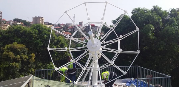
3.7 Meter Dual-Reflector Earth Station Antennas System
X- (Military/WGS), C-, or Ka-Band Capabilities
Type: DH 3.7 Meter DR Ku-band Antenna
3.7 Meter Dual-Reflector Earth Station Antenna Reflector incorporates stretch-formed doubly contoured panels with matched radials and hub for ease of field alignment. The standard designed azimuth over elevation pedestal provides a cost-effective for high stiffness and stability, full orbital arc coverage and fine drive performance, and ensures the pointing accuracy required for Ku-band operation. RF specifications can meet FCC 25.209, IESS and ITU-RS.580-5, INMARSAT, ASIASAT, INTELSAT, APT and Chinasat, etc.
High RF performance, LP adjustable feed
Galvanized steel parts/ Hot Dipped Galvanized
Type approval from: Intelsat/Asiasat/APT/Chinasat
Turning Head Pedestal El-over Az axis with jackscrew drive.
Different frequency ranges from many feed configurations
130km/h gusts to 200km/h High Operation Wind Option.
3.7 m RF & Antenna Specifications
| Ku-band Linear | Receive | Transmit |
|---|---|---|
| Frequency, GHz | 10.95-12.75 | 13.75-14.5 |
| Mid-Band Gain, dBi | 51.7 | 52.63 |
| VSWR | 1.3:1 | 1.3:1 |
| 3dB Beam Width, deg | 0.43 | 0.38 |
| Noise Temperature 10 Deg Elevation, K | 57 | |
| Noise Temperature 20 Deg Elevation, K | 50 | |
| Typical G/T @ 10 Degrees | 30.3 | |
| Port to Port Isolation Tx to Rx (same band),dB | 85 | |
| Tx Power Capability, KW | 2 | |
| Cross-pol. on Axis, dB | 35 | 35 |
| Insertion Loss, dB | 0.30 | 0.25 |
| Feed Interface | WR-75 CPR | WR-75 CPR |
| Radiation Pattern Compliance | FCC 25.209, ITU-RS.580-6, | |
| First sidelobe, dB | ≤ -14 | |
| Sidelobe Envelope | 32 – 25 log (1°≤θ<20°) | |
3.7 m Mechanical Specifications
| Mechanical Specifications | |
| Antenna Optics | Ring- focus design |
| Refector Aperture | 3.7 Meters (12Feet) |
| Reflector Panels | 12 precision-formed aluminum panels |
| Antenna Foundation | Reinforced Concrete Foundation, or Non-penetrating mount (NPM) |
| Mount Configuration | Turning Head Pedestal Elevation-over Azimuth axis configuration |
| Drive Type | Manual / Motorized jack screw |
| Surface Accuracy (RMS) | 0.5 mm |
| Finishes Reflector Surface | Aluminum panels with high-diffusing white paint |
| Pedestal & Reflector Backup Structure | Galvanized steel parts/ Hot Dipped Galvanized After Fabrication Galvanized |
| Elevation Travel | 0° to 90 ° Continuous, |
| Azimuth Travel | ±85° or 360°Continuous, |
| Pol. Travel | ±90°Continuous, |
3.7 m Environmental Performance
| Environmental Performance | |
| Operational Wind High Wind( option) | 45 mph (72 km/h) gusting to 60 mph (97 km/h) |
| Survival Wind | 125 mph (200 km/h), |
| Temperature | -40° C to +50° C |
| Humidity | 0-98% |
4.5 Meter Dual-Reflector Earth Station Antennas System
X- (Military/WGS), C-, or Ka-Band Capabilities
Type: DH 4.5 Meter DR Ku-band Antenna
4.5 Meter Dual-Reflector Earth Station Antenna Reflector incorporates stretch-formed doubly contoured panels with matched radials and hub for ease of field alignment. The standard designed azimuth over elevation pedestal provides a cost-effective for high stiffness and stability, full orbital arc coverage and fine drive performance, and ensures the pointing accuracy required for Ku-band operation. RF specifications can meet FCC 25.209, IESS and ITU-RS.580-5, INMARSAT, ASIASAT, INTELSAT, APT and Chinasat, etc.

Wide-band High RF performance, LP adjustable feed
Galvanized steel parts/ Hot Dipped Galvanized
Type approval from: Intelsat/Asiasat/APT/Chinasat
Turning Head Pedestal El-over Az axis with jackscrew drive.
130km/h gusts to 200km/h High Operation Wind Option.
Different frequency ranges from many feed configurations
4.5 m RF & Antenna Specifications
| Ku-band Linear | Receive | Transmit |
|---|---|---|
| Frequency, GHz | 10.95-12.75 | 13.75-14.5 |
| Mid-Band Gain, dBi | 53.2 | 54.5 |
| VSWR | 1.25:1 | 1.25:1 |
| 3dB Beam Width, deg | 0.35 | 0.3 |
| Noise Temperature 10 Deg Elevation, K | 51 | |
| Noise Temperature 20 Deg Elevation, K | 48 | |
| Typical G/T @ 10 Degrees | 32.4 | |
| Port to Port Isolation Tx to Rx (same band),dB | 85 | |
| Tx Power Capability, KW | 2 | |
| Cross-pol. on Axis, dB | 35 | 35 |
| Insertion Loss, dB | 0.30 | 0.25 |
| Feed Interface | WR-75 CPR | WR-75 CPR |
| Radiation Pattern Compliance | FCC 25.209, ITU-RS.580-6, | |
| First sidelobe, dB | ≤ -14 | |
| Sidelobe Envelope | 32 – 25 log (1°≤θ<20°) | |
4.5 m Mechanical Specifications
| Mechanical Specifications | |
| Antenna Optics | Ring- focus design |
| Refector Aperture | 4.5 Meters (14.7 Feet) |
| Reflector Panels | 12 precision-formed aluminum panels |
| Antenna Foundation | Reinforced Concrete Foundation, or Non-penetrating mount (NPM) |
| Mount Configuration | Turning Head Pedestal Elevation-over Azimuth axis configuration |
| Drive Type | Manual / Motorized jack screw |
| Surface Accuracy (RMS) | 0.5 mm |
| Finishes Reflector Surface | Aluminum panels with high-diffusing white paint |
| Pedestal & Reflector Backup Structure | Galvanized steel parts/ Hot Dipped Galvanized After Fabrication Galvanized |
| Elevation Travel | 0° to 90 ° Continuous, |
| Azimuth Travel | ±85° or 360° Continuous, |
| Pol. Travel | ±90° Continuous, |
4.5 m Environmental Performance
| Environmental Performance | |
| Operational Wind High Wind( option) | 45 mph (72 km/h) gusting to 60 mph (97 km/h) |
| Survival Wind | 125 mph (200 km/h), |
| Temperature | -40° C to +50° C |
| Humidity | 0-98% |
Feed and RF-chain configuration can be reviewed with the antenna
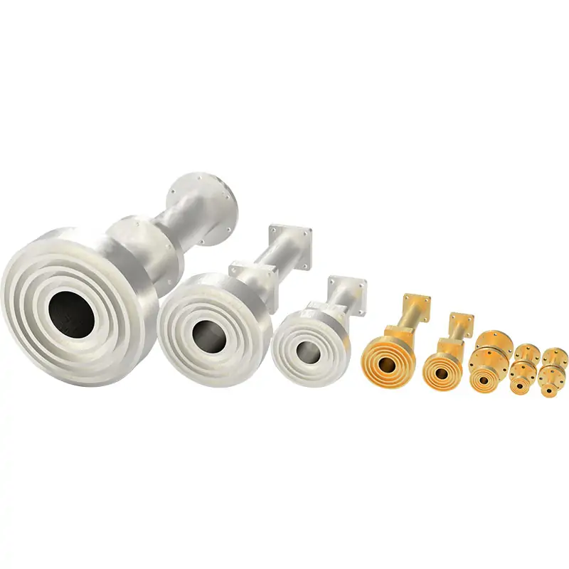
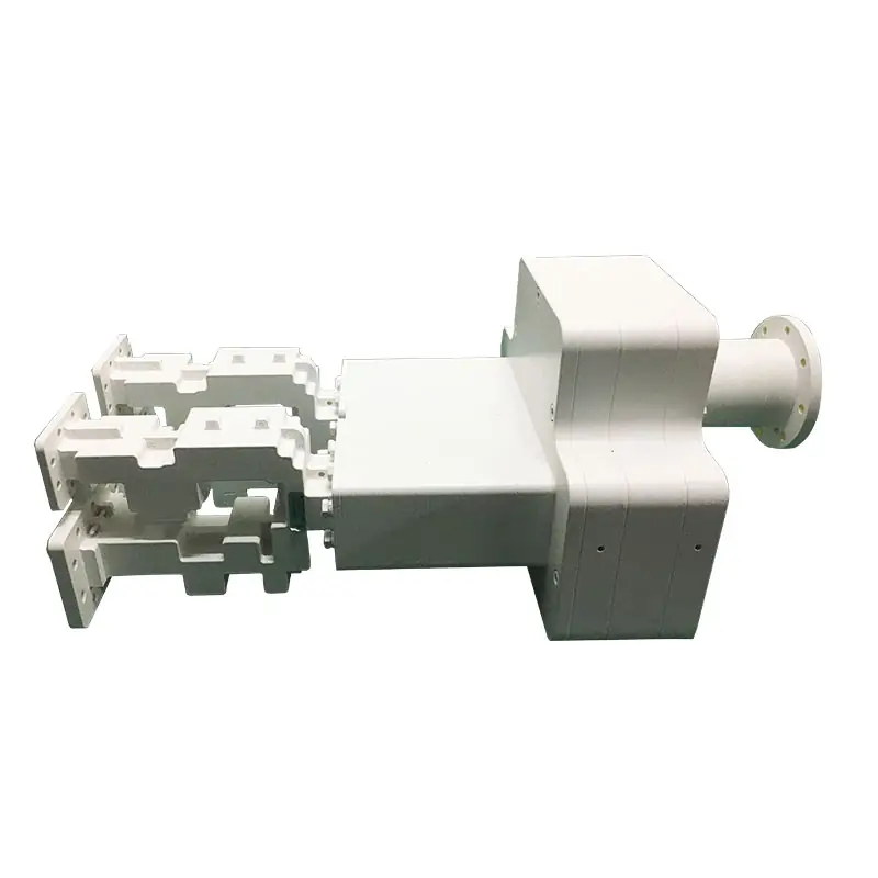
Dolph publishes feed-system capability for ring-focus and Cassegrain reflector antennas, including feed horns, OMTs, filters, diplexers, polarizers, rotary joints and complete RF networks. Single-band, dual-band and triple-band feed systems are available as custom work.
For the Ku-band antenna datasheets, the interface is WR-75 CPR. For other bands or multi-band operation, confirm the complete feed and waveguide interfaces before order.
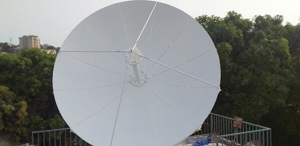
Manufacturing and test capability relevant to the RF chain
Dolph states that it was founded in 2001 and publishes in-house manufacturing capability for microwave components and feed systems. The company also publishes RF, antenna and environmental measurement capability used to verify components and assemblies.


Send these project details for a useful quotation
Frequency planExact receive and transmit ranges, including any non-Ku-band requirement.
Polarization and portsLinear or circular polarization, port count and isolation requirements.
Site and foundationGround or rooftop location, foundation constraint and available installation envelope.
Wind and environmentRequired operational and survival wind criteria, temperature and any deicing requirement.
Drive and controlManual or motorized jack screw, required travel and any controller or tracking requirement.
Acceptance documentsRequired RF test data, drawings, standard revision, satellite-operator requirement, quantity and schedule.
Choose another antenna when the project requirement changes

3.7 / 4.5 Meter Prime Focus Antenna
Use this range when a receive-only prime-focus configuration is a better fit than the dual-reflector Tx/Rx system.
View prime-focus option
6.2 / 7.3 Meter Large Size Antenna
For a larger dual-reflector aperture, compare the 6.2 m and 7.3 m systems when a 3.7 m or 4.5 m aperture does not meet the project link budget.
View larger dual-reflector optionWarranty and supplier information
Dolph Microwave was founded in 2001. The warranty covers defective material and workmanship for one year from delivery, with defective parts replaced and repair work required by normal use performed without charge within that period.
Company: Dolph Microwave Co., Ltd.
Contact: FengHuiNan Road NO.34, High-Tech Zone, Xi’an, China
Phone: +86 29 8881 0979
Email: [email protected]
Download Antenna Datasheets
Use the downloadable PDFs for the detailed 3.7 m and 4.5 m data. Final configuration, options, acceptance criteria and current approval status should be confirmed in the quotation and approved technical documents.