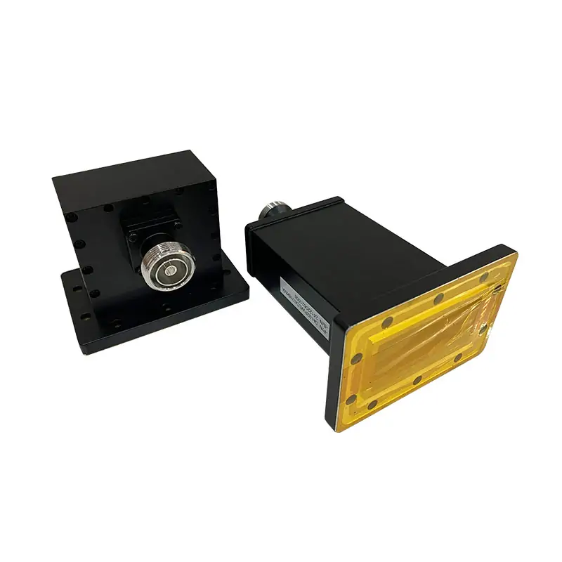
Waveguide to Coaxial Adapters
Right-angle and end-launch waveguide-to-coaxial adapters selected by waveguide size, operating band, coax connector, flange, power and mechanical orientation. Send both interfaces for model review.
Match the waveguide side and coax connector as one RF interface.
Dolph Microwave lists right-angle and end-launch waveguide-to-coaxial adapter configurations. Frequency, VSWR, insertion loss, power, connector and flange are model-specific and must be checked on the same row.
Request Adapter MatchingSend the details that control the final configuration

Waveguide side
Waveguide size, operating band and mating flange.
Coax side
Connector type, gender and impedance.
RF conditions
Frequency range plus average/peak power where applicable.
Orientation
Right-angle or end-launch and available installation envelope.
Keep family scope separate from the official model table.
The catalog overview references a wider WR2300-WR10 family, while the official model table lists WR1150-WR10 entries. Configurations outside the exact table require confirmation.
Official waveguide-to-coaxial adapter table
The official PDF provides model-specific frequency, WR size, VSWR, insertion loss, coax connector, power, flange, material and finish fields.
Open Official PDFHow to use the published data
Use one model row as a complete configuration. Do not combine the widest band, highest power and lowest VSWR from different rows.
Send both RF interfaces and the mechanical orientation.
A model match needs the waveguide/flange pair, coax connector/gender, operating band and power conditions. Include a drawing when connector orientation is controlled.
RFQ checklist
- Waveguide size and flange
- Coax connector, gender and impedance
- Operating band and power conditions
- Right-angle/end-launch orientation and envelope
Continue with the matching component family
Use when both sides remain coaxial.
Use when both sides remain waveguide interfaces.
Use when the coaxial path ends in a matched load.
Ready for a model check?
Send the operating conditions and interface requirements. We will return the next technical step.