Dolph Microwave
EIA & IEC Waveguide Flanges
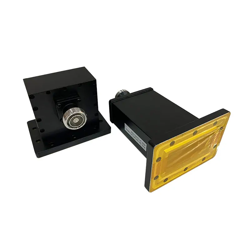
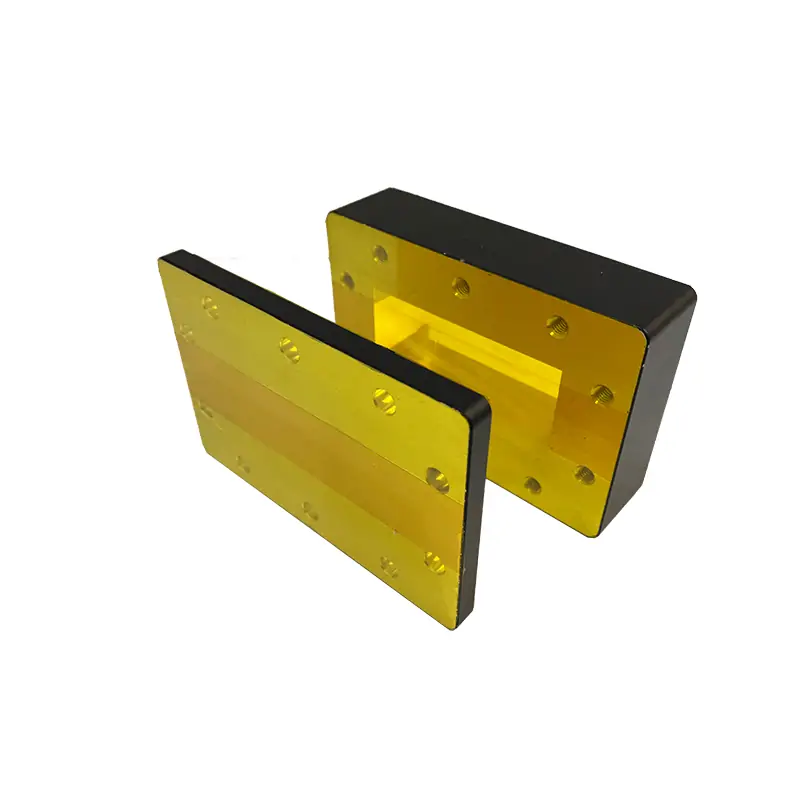
Dolph Microwave supplies waveguide flanges for joining compatible waveguide components at a defined mechanical interface. The EIA/IEC reference below relates WR and R waveguide designations to flange codes, including cover and grooved styles. Use it to identify an interface family, then confirm the dimensioned drawing for the mating pair.
A WR number identifies the waveguide size; it does not define the bolt pattern, alignment features, gasket groove or surface contact. For a replacement flange, send the full designation and a drawing or clear photograph of the mating face. For a new assembly, specify both ends before selecting associated seals or mounting hardware.
- Designation systems
- EIA / IEC
- Waveguide references
- WR / R
- Interface options
- Flat / grooved
For a standard rectangular waveguide assembly, check the flange together with the component band and aperture height.
Before you order
What needs to match at the joint?
Aperture and height
Confirm the internal opening and whether the waveguide is full-height or reduced-height. The standard size name alone does not cover every custom interface.
Bolt pattern and mating face
Include the hole positions, flange outline and cover/grooved face. A clear drawing avoids relying on a partial flange name.
Material and seal
The product information lists Aluminum 6061-T6 and custom groove options. Specify the required material and surface finish on the drawing, and identify any gasket, alignment pins or other mating hardware needed at the joint.
The EIA and IEC flange size guide explains designation and fit checks. For a thin interface component, compare waveguide flange shims.
For the rest of your setup
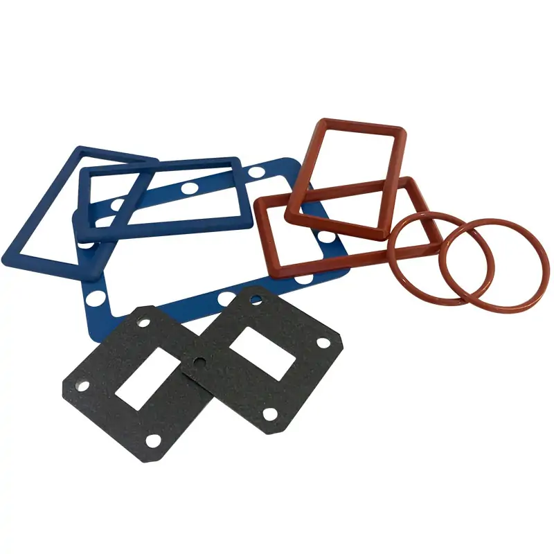
Specify the gasket with the flange
If the joint requires a seal, choose the gasket material and profile around the actual mating face. Pressure-only sealing and combined RF/pressure sealing call for different choices.
Compare die-cut waveguide gasketsTechnical data
Specifications & dimensions
This is a designation cross-reference, not a mating-compatibility certificate or a performance rating for every flange. Confirm the complete code, standard revision and drawing for the selected interface. Swipe or scroll across the table to see all columns.
| Frequency Range (GHz) | EIA Std. | IEC Std. | European IEC Standard Flanges | North American EIA Standard Flanges | |||||||||||||
|---|---|---|---|---|---|---|---|---|---|---|---|---|---|---|---|---|---|
| A-Style Round Flange | B-Style Square Flange | D-Style Rectangular Flange | E-Style Small Rectangular | B-Style Square Flange | D-Style Rectangular Flange | E-Style Small Rectangular | UG-Style | ||||||||||
| UAR | PAR | CAR | UBR | PBR | UDR | PDR | UER | SQ. COVER | SQ.COVER GROOVED | SQ. CHOKE | CPRF | CPRG | CMR | UG | |||
| 0.76-1.15 | WR975 | R9 | CPR975F | CPR975G | |||||||||||||
| 0.96-1.46 | WR770 | R12 | CPR770F | CPR770G | |||||||||||||
| 1.13-1.73 | WR650 | R14 | CPR650F | CPR650G | UG417A/U | ||||||||||||
| 1.45-2.2 | WR510 | R18 | CPR510F | CPR510G | |||||||||||||
| 1.72-2.61 | WR430 | R22 | CPR430F | CPR430G | UG435/U | ||||||||||||
| 2.17-3.3 | WR340 | R26 | UDR26 | PDR26 | CPR340F | CPR340G | |||||||||||
| 2.6-3.95 | WR284 | R32 | UAR32 | PAR32 | CAR32 | UDR32 | PDR32 | UER32 | UG-COVER | GROOVED | UG-CHOKE | CPR284F | CPR284G | UG53/U | |||
| 3.22-4.9 | WR229 | R40 | UAR40 | PAR40 | CAR40 | UDR40 | PDR40 | UER40 | CPR229F | CPR229G | CMR229 | ||||||
| 3.94-5.99 | WR187 | R48 | UAR48 | PAR48 | CAR48 | UDR48 | PDR48 | UER48 | UG-COVER | GROOVED | UG-CHOKE | CPR187F | CPR187G | CMR187 | UG149/U | ||
| 4.64-7.05 | WR159 | R58 | UAR58 | PAR58 | CAR58 | UDR58 | PDR58 | UER58 | CPR159F | CPR159G | |||||||
| 5.38-8.17 | WR137 | R70 | UAR70 | PAR70 | CAR70 | UDR70 | PDR70 | UER70 | UG-COVER | GROOVED | UG-CHOKE | CPR137F | CPR137G | CMR137 | UG344/U | ||
| 6.57-9.99 | WR112 | R84 | UBR84 | PBR84 | UDR84 | PDR84 | UER84 | UG-COVER | GROOVED | UG-CHOKE | CPR112F | CPR112G | CMR112 | UG51/U | |||
| 7.0-11.0 | WR102 | UBR102 | PBR102 | UDR102 | PDR102 | UER100 | UG-COVER | GROOVED | UG-CHOKE | ||||||||
| 8.2-12.5 | WR90 | R100 | UBR100 | PBR100 | UDR100 | PDR100 | UG-COVER | GROOVED | UG-CHOKE | CPR90F | CPR90G | CMR90 | UG39/U | ||||
| 9.84-15 | WR75 | R120 | UBR120 | PBR120 | UDR120 | PDR120 | UG-COVER | GROOVED | UG-CHOKE | CPR75F | CPR75G | ||||||
| 11.9-18 | WR62 | R140 | UBR140 | PBR140 | UDR140 | PDR140 | UG-COVER | GROOVED | UG-CHOKE | UG419/U | |||||||
| 14.5-22 | WR51 | R180 | UBR180 | PBR180 | UDR180 | PDR180 | UG-COVER | GROOVED | UG-CHOKE | ||||||||
| 17.6-26.7 | WR42 | R220 | UBR220 | PBR220 | UG-COVER | GROOVED | UG-CHOKE | UG595/U | |||||||||
| 21.7-33 | WR34 | R260 | UBR260 | PBR260 | UG-COVER | GROOVED | UG-CHOKE | UG1530 | |||||||||
| 26.3-40 | WR28 | R320 | UBR320 | PBR320 | UG-COVER | GROOVED | UG-CHOKE | UG599/U | |||||||||
| 32.9-50.1 | WR22 | R400 | UG-COVER | GROOVED | UG-CHOKE | UG383/U | |||||||||||
| 39.2-59.6 | WR19 | R500 | UG383/U | ||||||||||||||
| 49.8-75.8 | WR15 | R620 | UG385/U | ||||||||||||||
| 60.5-91.9 | WR12 | R740 | UG387/U | ||||||||||||||
| 73.8-112 | WR10 | R900 | UG387/U | ||||||||||||||
| 92.2-140 | WR8 | R1200 | UG387/U | ||||||||||||||
| 113-173 | WR6 | R1400 | UG387/U | ||||||||||||||
| 145-220 | WR5 | R1800 | UG387/U | ||||||||||||||
| 172-261 | WR4 | R2200 | UG387/U | ||||||||||||||
| 217-330 | WR3 | R2600 | UG387/U | ||||||||||||||
| 325-500 | WR2 | UG387/U | |||||||||||||||
| 750-1100 | WR1 | UG387/U | |||||||||||||||
Materials & ordering options
Technical documents
Questions before ordering
Will any two WR75 flanges connect?
The WR designation describes the waveguide size. The mating flange code, bolt pattern, aperture height and face geometry still need to agree.
Can you quote a non-standard flange?
Send a dimensioned drawing with the material, surface finish, mating part and operating conditions. The custom interface can then be reviewed as a specific part.
Related products
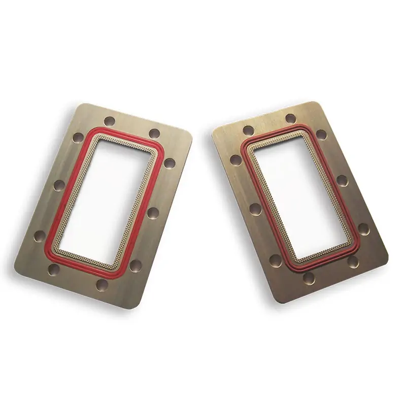
Waveguide Flange Shim
View productFor shim dimensions at a waveguide interface.
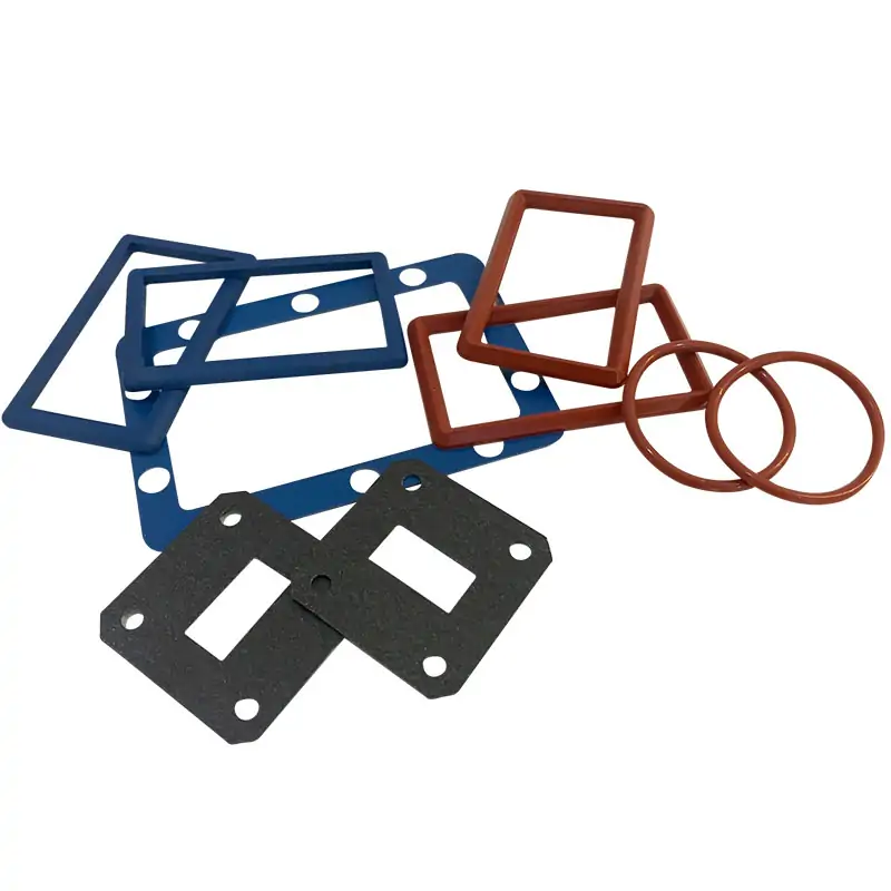
Waveguide Gasket and O-Ring
View productFor groove-fitting and other seal profiles.
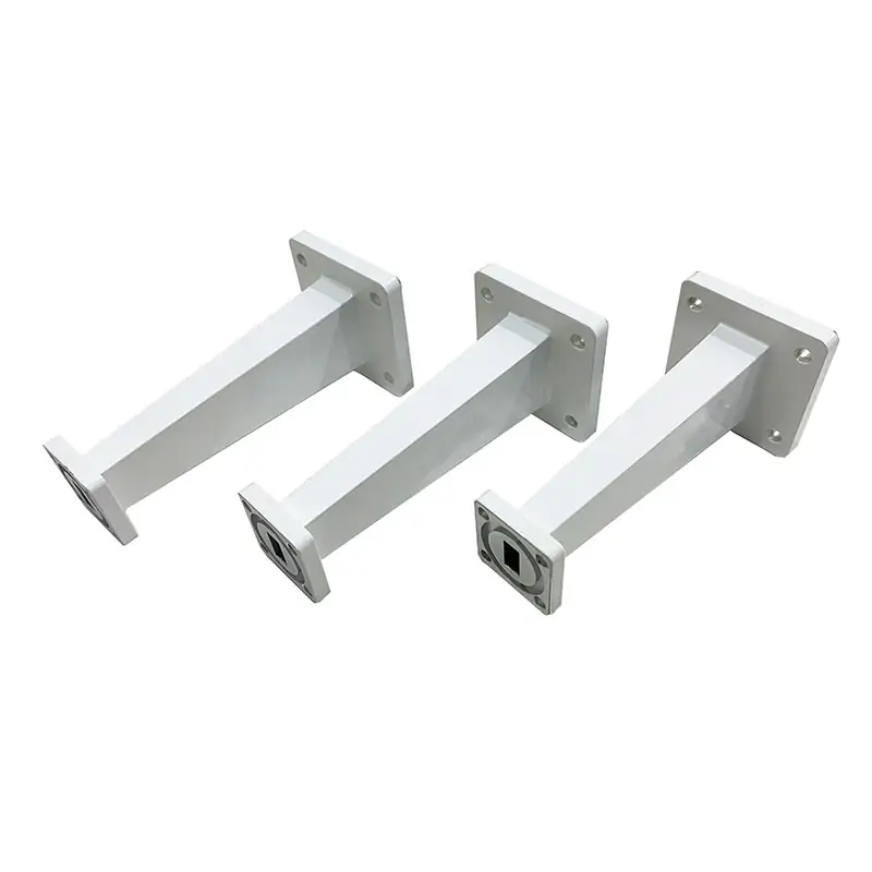
Waveguide Transitions
View productFor a change in waveguide size or interface.
Tell us what you need
Have a model or drawing?
Send the WR/R designation, full flange code, dimensioned mating drawing, material, finish and quantity. Include aperture height, bolt and alignment-pin details, seal requirements, and any pressure or temperature conditions. Identify whether the request is for loose flanges or an assembled waveguide part.