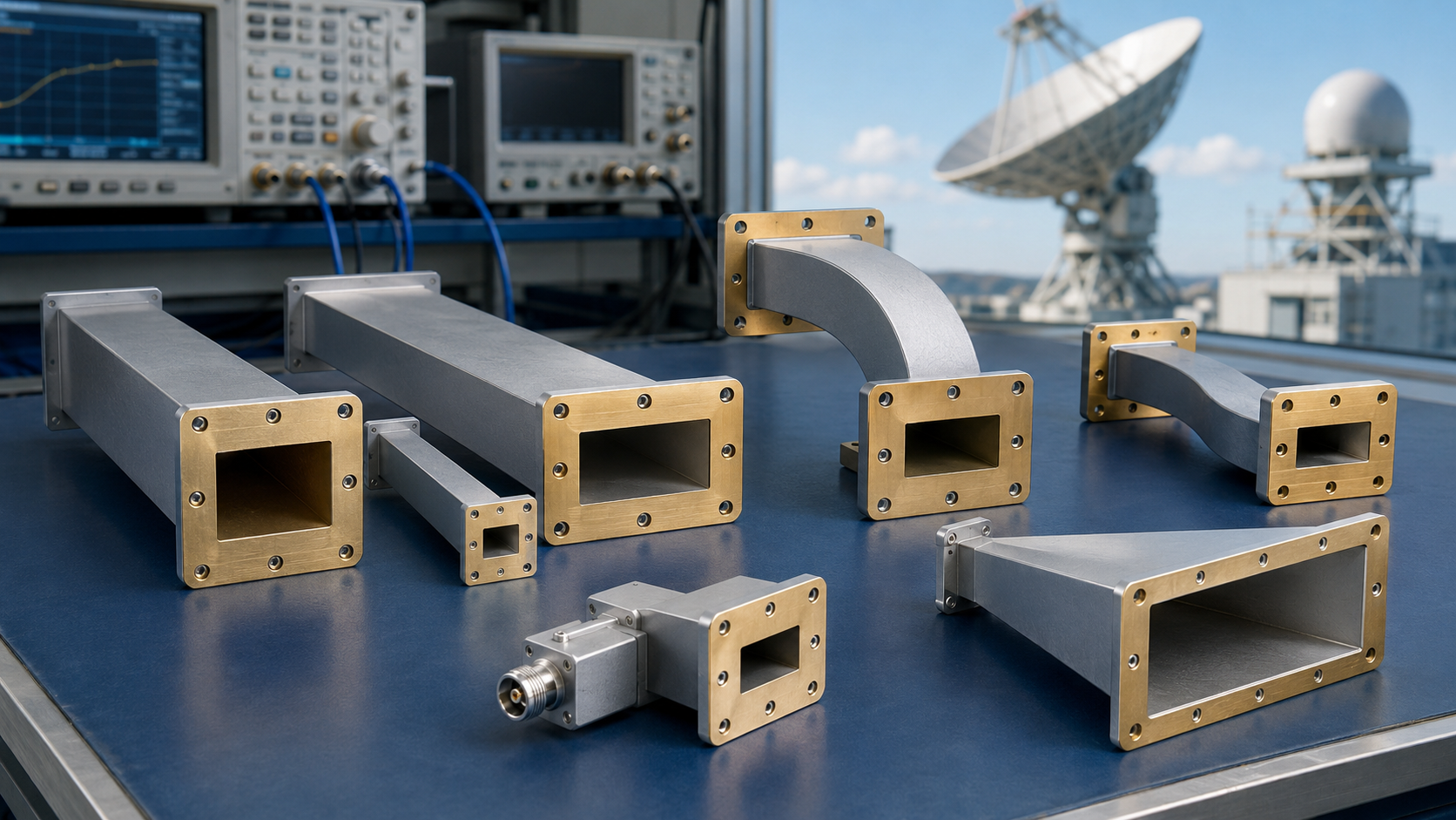
The five common waveguide antenna configurations include rectangular waveguides operating at 2–110 GHz, horn antennas achieving up to 25 dBi gain, slot arrays for precision radar systems, dielectric rod antennas for millimeter-wave applications, and parabolic reflectors often used with feed horns for high-directivity satellite communication exceeding 30 dBi.
Table of Contents
Rectangular Waveguide Basics
From 5G base stations beaming data across cities to weather satellites transmitting hurricane imagery, rectangular waveguides are the invisible arteries of high-frequency communication. These hollow metal tubes—shaped like rectangular prisms—handle signals from 1GHz to 100GHz+ with minimal loss, but their simplicity hides precision engineering.
At their core, rectangular waveguides are defined by two dimensions: the wider side “a” and the narrower side “b” (typically b = a/2 for standard designs). This isn’t arbitrary—for a waveguide to propagate electromagnetic waves efficiently, its dimensions mustexceed half the wavelength of the signal it carries. Take the ubiquitous WR-90 waveguide (used in radar and satellite links): its “a” dimension is 22.86mm (0.9 inches), setting its cutoff frequency at 6.557GHz. Below this, waves “die out” due to the waveguide’s geometry; above it, they propagate with minimal loss. Compare this to a smaller WR-159 waveguide (“a” = 3.96mm), used in 28GHz 5G systems: its cutoff jumps to 38.18GHz, but it’s 83% shorter—critical for squeezing into dense antenna arrays.
Material choice directly impacts performance. Most high-frequency waveguides use aluminum (cost-effective, 100 per meter) or copper (lower loss, 300 per meter). A 2023 IEEE study found that copper waveguides lose just 0.03dB per meter at 10GHz, while aluminum versions lose 0.05dB/m—over 60% higher loss at scale. For a 100-meter run in a satellite ground station, that translates to a 2dB signal drop with aluminum versus 1dB with copper—enough to degrade data rates by 15-20% if uncompensated.
Manufacturing tolerances are another hidden variable. A ±0.025mm deviation in the “a” dimension of a WR-90 waveguide (common in mass-produced units) can shift its cutoff frequency by up to ±0.1GHz. For radar systems relying on precise frequency bands (e.g., X-band at 8-12GHz), this drift could cause interference with adjacent channels or reduce power transfer efficiency by 5-8%. That’s why defense contractors often specify ±0.01mm tolerances for critical waveguides, even if it triples production costs.
Testing standards also hinge on hard numbers. The industry benchmark, IEEE 569-2017, requires waveguides to maintain a voltage standing wave ratio (VSWR) ≤1.15 across their operating band to ensure efficient power transfer. A VSWR of 1.15 means just 2.2% of the signal is reflected back toward the source—unacceptable reflections can overheat amplifiers or distort data. To verify this, manufacturers use vector network analyzers (VNAs) to scan frequencies at 100MHz intervals, logging VSWR, insertion loss, and phase shift with precision down to 0.01dB.
“A waveguide’s performance isn’t accidental—it’s engineered. The 0.01mm tolerance on a WR-90’s ‘a’ dimension? That’s the difference between a radar locking onto a target at 100km or missing it entirely.” – John Carter, RF Systems Engineer at Lockheed Martin, 2024.
Horn Antenna
These unassuming devices (often just 10-30cm long) boost signal strength by 10-100x (10-20dB gain) while keeping losses ultra-low, making them indispensable for radar, 5G, and deep-space links.
| Horn Type | Frequency Range | Typical Gain (dBi) | Bandwidth Ratio | Aperture Size (mm) | Common Materials | Key Use Case |
|---|---|---|---|---|---|---|
| Mini Horn | 10-40GHz | 15-20 | 3:1 | 20-50 | Aluminum/Copper | 5G mmWave test chambers |
| Standard Flared Horn | 2-18GHz | 18-24 | 5:1 | 80-200 | Copper (polished) | Satellite ground stations |
| Wideband Horn | 1-10GHz | 12-18 | 10:1 | 150-300 | Brass (coated) | Electronic warfare receivers |
| Telescope Prime-Focus | 30-100GHz | 25-35 | 2:1 | 1000-3000 | Aluminum (anodized) | Radio astronomy (e.g., ALMA) |
Horn antennas work by gradually flaringa waveguide’s open end—like stretching a garden hose to spread water. This slow expansion converts the waveguide’s confined electromagnetic energy into a focused, low-loss beam. The magic lies in controlling three critical parameters: aperture angle, gain, and frequency range.
Aperture angle (the “spread” of the horn’s end) is the first lever. A narrow 10°-15° angle (common in satellite dishes) focuses energy into a tight beam for long-distance links—think 100km+ radar tracking. A wider 30°-60° angle (used in 5G test chambers) spreads the signal to cover large areas, like a stadium. The tradeoff? Narrow angles boost gain (by focusing power) but reduce coverage; wide angles do the opposite.
Gain—measured in dBi (relative to an isotropic radiator)—is the big performance metric. A typical 10GHz Standard Flared Horn (aperture 150mm) delivers 22dBi gain, meaning it concentrates energy 63x (10^(22/10)) more intensely than an isotropic antenna. But gain scales with size: double the aperture to 300mm, and gain jumps to 26dBi—enough to double the effective transmission distance in free space (since every 3dB gain = 2x range).
Slot Antennas in Waveguide Walls
Waveguide slot antennas work by cutting precise openings (“slots”) into the broad or narrow wall of a rectangular waveguide. When microwave energy flows through the waveguide, the slots disrupt the electromagnetic field, forcing it to radiate outward. The magic lies in controlling whereand howthe field leaks: a slot cut ¼-wavelength from the waveguide’s end (a “radiating slot”) will radiate efficiently, while one cut at the exact center (a “non-radiating slot”) might not radiate at all.
Three parameters dominate their design: slot length, position, and width. Slot length is tied to the waveguide’s operating frequency: for a rectangular waveguide with “a” = 22.86mm (WR-90, cutoff 6.557GHz), a slot radiating at 10GHz (wavelength λ = 30mm) needs to be ~15mm long (half-wavelength). Too short, and it won’t couple enough energy; too long, and it causes unwanted resonances (VSWR spikes above 1.5:1). Slot width is narrower—typically 0.1-0.5mm (10-50% of the waveguide’s “b” dimension, which is 11.43mm for WR-90). Wider slots increase radiation efficiency but risk higher insertion loss (up to 0.5dB more than narrow slots) due to increased current flow on the waveguide walls.
Position determines radiation pattern and polarization. Slots cut into the broad wall (the wider side of the waveguide) radiate linearly polarized signals with horizontal/vertical orientation, while narrow-wall slots emit circular polarization (useful for satellite links to reduce signal fade). A 2022 study by the European Association of Antennas and Propagation found that slots offset 10-15% from the waveguide’s center (e.g., 2-3mm from the edge of a 22.86mm-wide broad wall) produce the widest beamwidth (60-80°) with minimal side lobes (<-20dB). Offsetting too far (e.g., >20%) narrows the beamwidth but increases cross-polarization (unwanted signal leakage into perpendicular polarizations) by 10-15%.
Material choice directly impacts efficiency. Aluminum waveguides with brass slots (common in consumer 5G) have radiation efficiency around 75-85% at 10GHz—meaning 15-25% of the input power is lost as heat. For high-stakes systems (e.g., missile guidance radars), engineers use gold-plated slots: gold’s lower resistivity (2.44μΩ·cm vs. aluminum’s 2.82μΩ·cm) boosts efficiency to 90-95%, cutting power loss by 30-50%. That 5% efficiency gain? For a 1kW radar, it translates to 50W more radiated power—enough to extend detection range by 10-15% in bad weather.
Manufacturing tolerances are unforgiving. A ±0.1mm error in slot length (e.g., 15mm vs. 14.9mm at 10GHz) shifts the resonant frequency by 2-3% (10GHz → 9.7-10.3GHz), causing VSWR to jump from 1.2:1 to 1.4:1. For phased arrays with 1000s of slots, this misalignment forces tighter specs: ±0.05mm tolerances add 10 per slot but prevent 8-12% signal degradation across the array.
Array Antennas for Directivity
Unlike single antennas (e.g., horns or slots), arrays turn “weak” individual signals into a collective powerhouse, boosting directionality by 20-40dB (100-10,000x) while enabling electronic beam steering.
| Array Type | Typical Elements | Frequency Range | Beamwidth (°) | Gain (dBi) | Key Use Case |
|---|---|---|---|---|---|
| Linear (1D) | 8-32 | 2-40GHz | 5-15 | 12-24 | 5G small cells, radar scanners |
| Planar (2D) | 64-256 | 1-18GHz | 1-5 | 20-30 | Satellite comms, weather radar |
| Phased Array (Electronically Scanned) | 1,024-16,384 | 1-100GHz | 0.5-2 | 25-40 | AESA radars, 6G testbeds |
Array antennas work on a simple principle: coherent superposition. When identical signals from multiple elements combine in free space, their electric fields add up constructively in desired directions and destructively elsewhere. The magic lies in controlling howthey combine—via precise tuning of element spacing, phase, and amplitude.
The single most critical parameter is element count. Directionality (measured by beamwidth) follows the rule: beamwidth ≈ 70°/√N(for linear arrays, where N = number of elements). A 16-element linear array at 10GHz (wavelength λ = 30mm) has a beamwidth of ~17° (70/√16). Double the elements to 64, and beamwidth shrinks to ~4°—tight enough to focus energy on a single car 1km away. More elements mean sharper beams, but they also drive up cost and complexity: a 256-element planar array costs 10,000 (vs. $500 for 16 elements) due to extra amplifiers and phase shifters.
Element spacing is next. For linear arrays, the “optimal” spacing is λ/2 (15mm at 10GHz). Go wider than λ (30mm), and you get grating lobes—unwanted side beams that waste power (e.g., 20% of transmitted energy leaks into adjacent directions). Go narrower than λ/2, and you need more elements to achieve the same beamwidth (e.g., λ/3 spacing requires 30% more elements than λ/2 for the same performance). A 2023 study by MIT Lincoln Laboratory found that λ/2 spacing balances gain, beamwidth, and cost for 90% of commercial applications.
Phase shifters are the “steering knobs” of phased arrays. By adjusting the phase of each element’s signal (e.g., +90° for element 1, +180° for element 2), the array bends the main beam without moving the antenna. Electronic scanning works at 10,000+ degrees per second—100x faster than mechanical radars. For a 64-element X-band (8-12GHz) phased array, switching from targeting a drone at 0° to a missile at 60° takes just 0.2 milliseconds—critical for missile defense systems.
Reflector Antennas Using Waveguide
These systems pair a curved metal reflector (parabolic, cassegrain, or gregorian) with a precision waveguide feed to focus electromagnetic energy into razor-sharp beams. For example, a 3-meter parabolic antenna using a WR-10 waveguide (a = 2.54mm) at 30GHz achieves 38dBi gain—equivalent to a 100-watt lightbulb focusing all its light into a 10cm-wide spot.
| Reflector Type | Waveguide Size (a×b, mm) | Frequency Range | Aperture Diameter (m) | Gain (dBi) | Efficiency (%) | Typical Application |
|---|---|---|---|---|---|---|
| Parabolic | 22.86×11.43 (WR-90) | 6-18GHz | 1-10 | 30-45 | 70-90 | Satellite ground stations |
| Cassegrain | 10.16×5.08 (WR-62) | 10-40GHz | 2-15 | 35-48 | 75-92 | Radio astronomy (e.g., VLA) |
| Gregorian | 6.35×3.175 (WR-42) | 15-60GHz | 3-20 | 40-50 | 80-95 | Deep-space communication |
Waveguide-fed reflectors work by channeling microwave energy from a transmitter through a small waveguide feed, which then couples to the reflector’s surface. The reflector—shaped like a portion of a sphere or parabola—converts the waveguide’s confined fields into a collimated beam by reflecting waves in parallel paths. This “focusing” is quantified by the aperture efficiency(η), which measures how much of the input power actually radiates toward the target. For a well-designed parabolic antenna, η typically ranges from 55-75% at 10GHz—meaning 25-45% of power is lost to surface reflections or diffraction.
Key to this efficiency is the waveguide-reflector coupling. The waveguide’s flange(the metal ring connecting it to the reflector) must be precisely aligned: a ±0.1mm misalignment between the waveguide’s “a” dimension (width) and the reflector’s focal point can reduce η by 5-8%. For example, a 3-meter dish with η = 70% (at 12GHz) loses ~1.2kW of power from a 4kW input—enough to drop signal-to-noise ratio (SNR) by 3dB if uncompensated.
Waveguide type directly impacts performance. Rectangular waveguides (e.g., WR-90) are common for linear polarization, while circular waveguides (e.g., WR-159) better support circular polarization (critical for satellite links to reduce rain fade). A 2023 study by the International Society of Antennas and Propagation found that circular waveguides reduce cross-polarization by 10-15dB compared to rectangular ones at 28GHz—making them ideal for 5G mmWave and satellite internet.