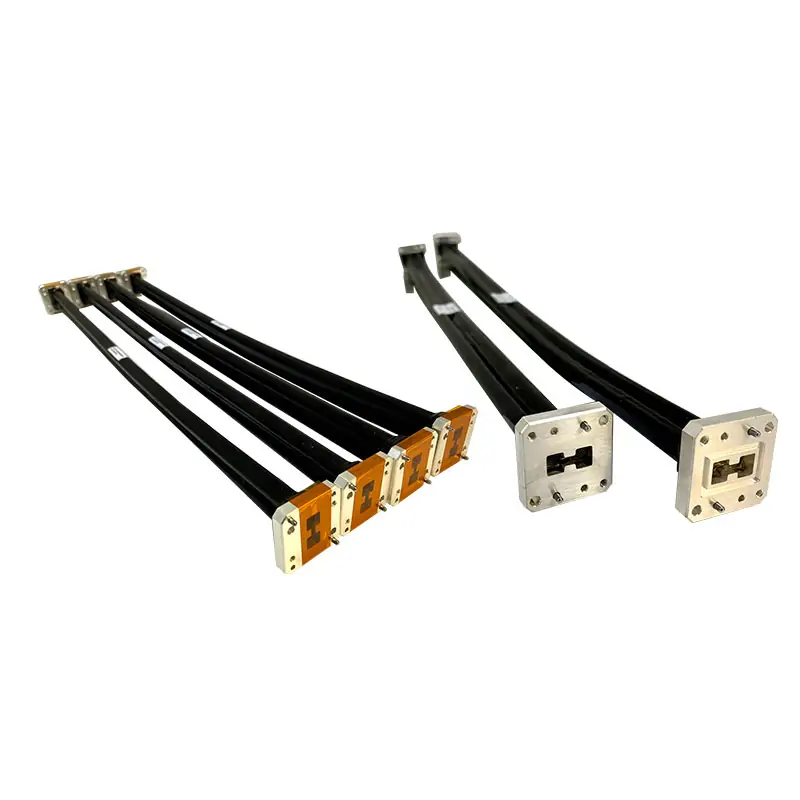
Double-Ridged Flexible Waveguide – Twistable & Non-Twistable WRD Assemblies
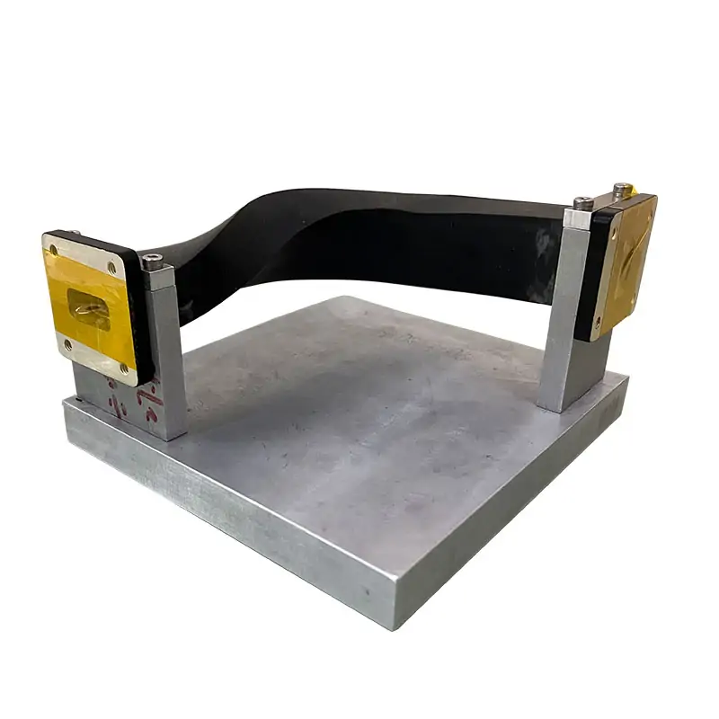
Dolph Microwave supplies flexible double-ridged waveguide assemblies with cover or grooved flanges. Published models cover 5.8–40.0 GHz across WRD580, WRD650, WRD750 and WRD180, with model-specific VSWR, insertion loss, bend radius and average power data. Preformed and hybrid flex-rigid configurations can be reviewed against your drawing and mating interfaces.
Published Product Summary
The product summary above and the detailed model tables below are both retained as published. Final length, power, flange and mechanical configuration should follow the selected model and approved drawing.
Double-Ridged Flexible Waveguide Model Specifications
Match the complete operating band, WRD interface, flange designation and minimum bend radius to the required installation.
| MODEL | FREQ. RANGE (GHz) | WG SIZE | VSWR | IL (dB/m) | FLANGES TYPE | MIN. BENDING RADIUS | CORE MATERIAL | JACKET TYPE | FINISH | DATASHEET | ||
|---|---|---|---|---|---|---|---|---|---|---|---|---|
| COVER | GROOVED | E-(mm) | H-(mm) | |||||||||
| DH-580DRWEL… | 5.8-16.0 | WRD580 | 1.25:1 | 1.5 | FPWRD580D28 | FMWRD580D28 | 105 | 210 | Brass / BeCu | Silicone | Silver Plated | PDF STEP |
| DH-650DRWEL… | 6.5-18.0 | WRD650 | 1.3 | 1.65 | FPWRD650D28 | FMWRD650D28 | 90 | 180 | Brass / BeCu | Silicone | Silver Plated | PDF STEP |
| DH-750DRWEL… | 7.5-18.0 | WRD750 | 1.3 | 1.65 | FPWRD750D24 | FMWRD750D24 | 85 | 170 | Brass / BeCu | Silicone | Silver Plated | PDF STEP |
| DH-180DRWEL… | 18.0-40.0 | WRD180 | 1.5 | 3.42 | FPWRD180C24 | FMWRD180C24 | 55 | 110 | Brass / BeCu | Silicone | Silver Plated | PDF STEP |
Datasheet Construction & Power Data
Average power, insertion loss, bend radius, flange, finish and material are model-specific.
| Model | IL Max. (dB/m) | Power Rating Avg.(W) | Min. Bending Radius E-(mm) | H-(mm) | Flange Type | Inside Finish | Body Finish | Material |
|---|---|---|---|---|---|---|---|---|
| DH-580DRWEL… | 1.5 | 300 | 105 | 210 | Cover/Grooved | Chromate Conversion/Silvering | Jacket / without jacket. | Brass |
| DH-650DRWEL… | 1.65 | 100 | 90 | 180 | Cover/Grooved | Chromate Conversion/Silvering | Jacket / without jacket. | Brass |
| DH-750DRWEL… | 1.65 | 100 | 85 | 170 | Cover/Grooved | Chromate Conversion/Silvering | Jacket / without jacket. | Brass |
| DH-180DRWEL… | 3.42 | 50 | 55 | 110 | Cover/Grooved | Chromate Conversion/Silvering | Jacket / without jacket. | Brass |
Part Number Guide
Datasheet Ordering Information
Assembly Options, Lengths & Accessories
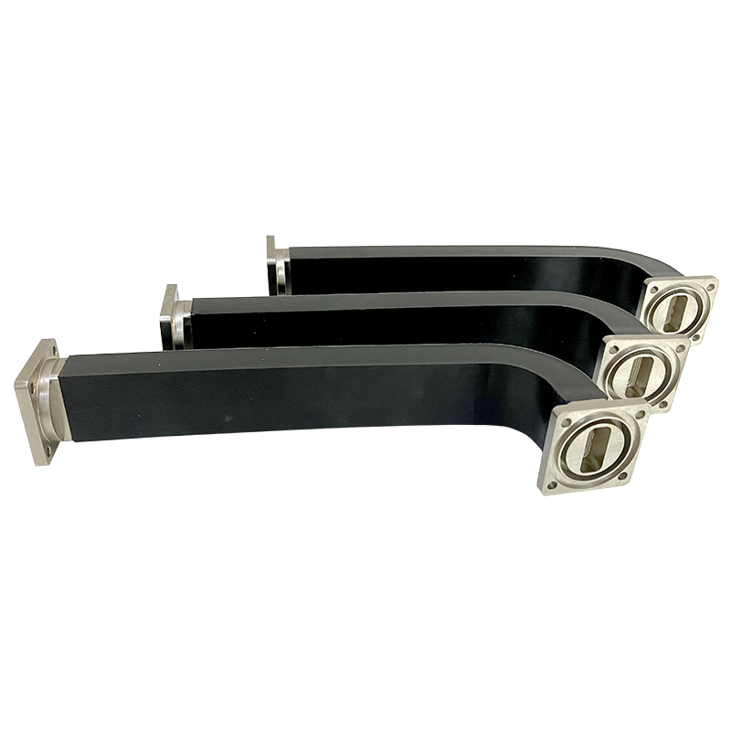
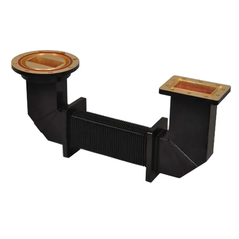
Preformed & Hybrid Assemblies
Available Preformed bend and hybrid flexible waveguide assemblies.
Length of Flexible Twistable Assemblies
The standard recommended length for the various waveguide sizes. MM: 300, 500, 600, 900, 1000, 1200 and 1500. Other lengths may be available on request but may be subject to tooling and design charges.
Accessories
Hardware, fixing and clamping kit accessories are available for use with our flexible waveguide products.
Match the Flexible Section to the Rest of the RF Path
Use Rigid WRD Sections Where Flexibility Is Not Needed
For fixed straight routing, review the Double-Ridged Waveguide Tube. For fixed direction changes, review Double-Ridged Waveguide Bends.
Source a Complete Waveguide Route
For mixed straights, bends, transitions, flexible sections or replacement work, review Custom Waveguide Assemblies and the Waveguide Components sourcing overview. If the interface is standard rectangular rather than WRD, see Seamless Flexible WG.
Manufacturing and Order Support
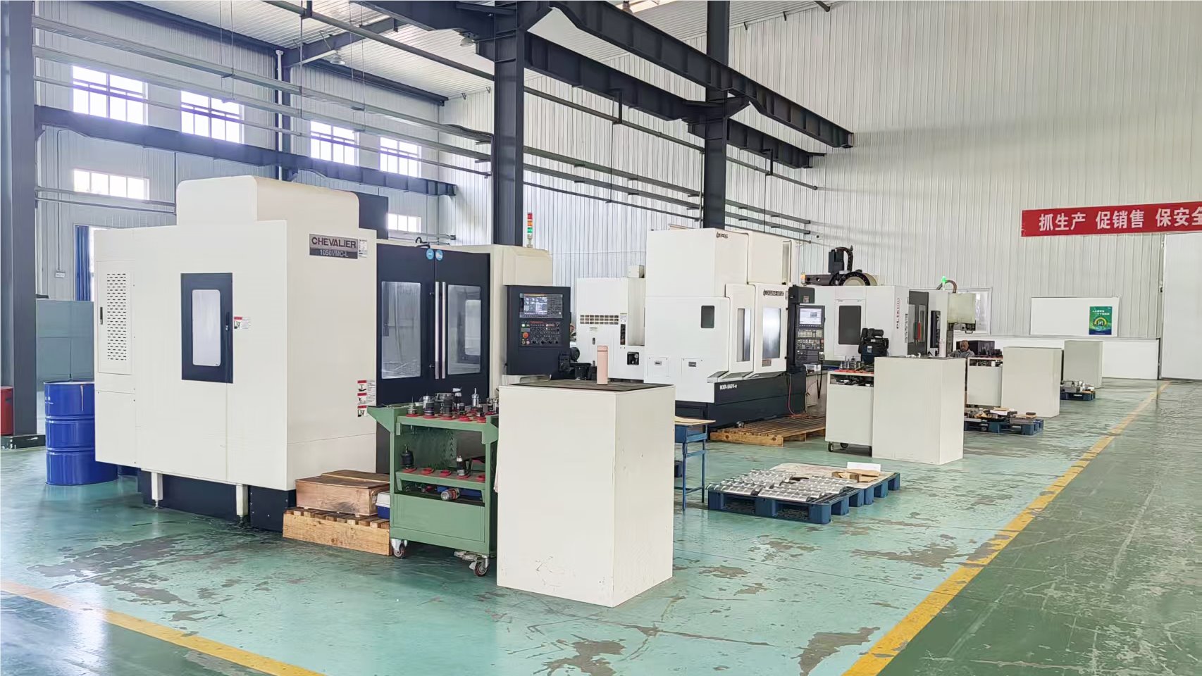
Dolph Microwave has manufactured microwave components and antenna feed systems since 2001 in Xi’an, China. Published factory capabilities include CNC machining, waveguide forming and bending, soldering and brazing, plating, assembly and dimensional inspection.
Drawing-based review: Send a PDF, STEP file, sketch, mating-part data or existing part number.
Acceptance requirements: State which dimensional, inspection and RF records are required before quotation.
Warranty: The website states a one-year warranty against defective material and workmanship from delivery, subject to the published terms.